Saturday, 21 September 2013

Atmel AVR ISP Microcontroller Programmer Project

One of the frustrating part in learning AVR microcontroller for the beginners is the AVR microcontroller programmer. The question is how to program my AVR mircrocontroller; actually if you googling on the internet and search for AVR ISP Programmer there are plenty information; start from simply using your PC parallel port to the sophisticated Atmel owned AVRISP mkII programmer. This will rise another question; which one should I choose? Well, if you are looking for the Atmel AVR programmer you have to consider how many AVR devices does this programmer software support and how this programmer hardware will connect to your PC/Notebook, of course the best and the complete one will be the Atmel own AVR programmer.
The well known open sources AVR ISP programmer is released by Atmel called AVR911: AVR Open-source Programmer (is that just a coincident they use the number 911, therefore you can see how important this topics is) and the hardware schema you could find on their application note AVR910: In-System Programming. The original schema use the old AT90S1200 and both the firmware (at90isp_ver23.asm) and the downloader (AVROSP.exe) only support a view old devices, fortunately there are peoples out there that keep this application note updated with the current devices.

In this project I will use the AVRJazz Tiny2313 board from ermicro as the basic board for the programmer and AVR ATtiny13 microcontroller as the target for the programmer. The firmware is taken from Klaus Leidinger at mikrocontroller-projekte.de and I made some modification to the source code, so it can work with AVRJazz Tiny2313 board; this little changes is mainly on the ATTiny2313 microcontroller type (originally AT90S2313), crystal oscillator frequency (originally 7.3728 mHz), the LED’s routines (originally using dual color LED attached to the PORT B3 and B0) and the healcheck function to blink the board’s LED 5 times when it start. For the complete source code and the hex code you can download from here.
Although the firmware can work very well with the Atmel’s AVRPROG that come with the AVR Studio 4 (from menu Tools -> Avr Prog…), but this programmer only support a view devices; beside Atmel look likes will not update this program anymore, the last time they update the AVRPROG (version 1.40) mainly just for supporting their new AVR Butterfly evaluation board which is using ATMega169. Therefore I choose AvrOspII from Mike Henning for the latest windows programmer version that supporting the AVR911 protocol; this programmer software support mostly used AVR microcontroller devices.
The following is the hardware diagram, cable connection from PORTB AVRJazz Tiny2313 board (see the AVRJazz Tiny2313 schema above) and the schema for ATtiny13 used in this project:


For the purpose of this project I will use the AVR ATtiny13 fast PWM mode feature for dimming the LED1 connected to the PIN 5 (OC0A); the following is the AVR assembler code:
;*********************************************************************
; Program       : tiny13pwm.asm
; Description   : Tiny13 Fast PWM Mode demo
; Last Updated  : 30 November 2008
; Author        : RWB
; IDE/Compiler  : Atmel AVR Studio 4.14
; Programmer    : AvrOspII v5.47 from Mike Henning
;               : AVRJazz Tiny2313 Board with firmware
;               : Avr910_2313_v38b_01.asm Modified by RWB from
;               : Klaus Leidinger(mikrocontroller-projekte.de)
;*********************************************************************
.include "tn13def.inc"
; The Tiny13 Default Frequency Clock
.equ F_CPU = 9600000
.cseg
; Start on the flash ram's address 0
.org 0
main:   ldi R24,RAMEND         ; Initial Stack Pointer
 out SPL,R24            ; SP = RAMEND
; Initial I/O
        ldi   R16,0xFF
        out   DDRB,R16         ; DDRB=0xFF
; Initial PWM
        ldi   R16,0b10000011
 out   TCCR0A,R16       ; TCCR0A = 0b10000011
 ldi   R16,0b00000001
 out   TCCR0B,R16       ; TCCR0B = 0b00000001
repeat: ldi   R16,255          ; R16 = 255
bright: inc   R16              ; R16 = R16 + 1
        out   OCR0A,R16        ; OCR0A = R16
 ldi   R19,1
 rcall delay_func       ; Call Delay Function Parameter R19 = 1
        cpi   R16,255
 brne  bright           ; if (R16 <> 255) goto bright label
 out   OCR0A,R16        ; OCR0A = R16
 ldi   R19,1
 rcall delay_func       ; Call Delay Function Parameter R19 = 1
 clr   R16              ; R16 = 0
dark:   dec   R16              ; R16 = R16 - 1
        out   OCR0A,R16        ; OCR0A = R16
 ldi   R19,1
 rcall delay_func       ; Call Delay Function Parameter R19
        cpi   R16,0
 brne  dark             ; if (R16 <> 0) goto dark label
 out   OCR0A,R16        ; OCR0A = R16
 ldi   R19,50
 rcall delay_func       ; Call Delay Function Parameter R19
 rjmp  repeat
; Simple Delay Function
delay_func:
delay0: ldi   R20,25     ; R20 = 25
delay1: ldi   R21,255    ; R21 = 255
delay2: dec   R21        ; Descrease R21
 brne  delay2     ; if (R20 != 0) goto delay2 label
        dec   R20        ; Decrease R20
        brne  delay1     ; if (R20 != 0) goto delay1 label
 dec   R19        ; Decrease R19
 brne  delay0     ; if (R19 != 0) goto delay0 label
 ret              ; Return to the caller
.exit

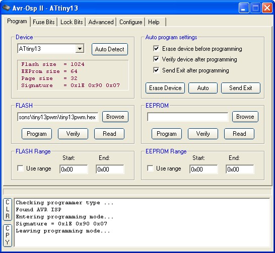
After compiling the sample code above on the AVR Studio 4 than start the AvrOspII program; if all connected then the programmer will automatically detect the target ATtiny13 microcontroller or you can click the Auto Detect button.


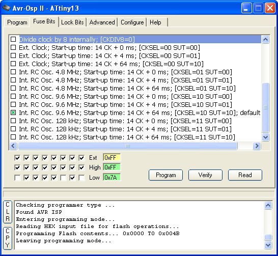
Before you download the hex program check the Fuse Bits on the Fuse Bits tab, make sure you uncheck the Divide clock by 8 internally; [CKDIV8=0] and use the default Internal RC oscillator 9.6 Mhz, click the Program button to change the Fuse Bits and click the Read button again to make sure it’s already change.


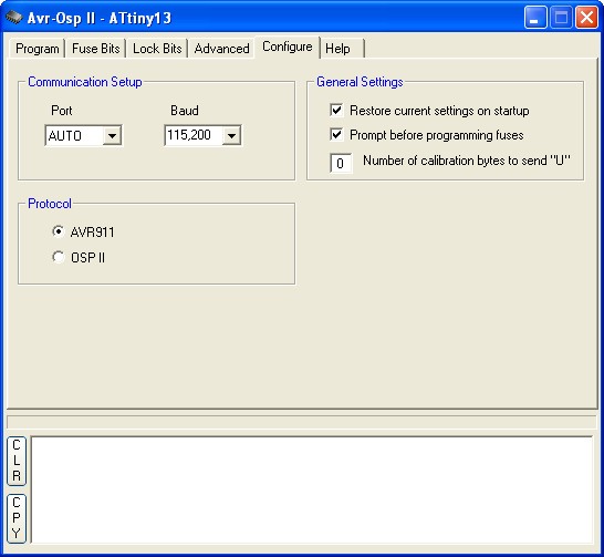
Also check the configuration on the Configure tab as follow:


The Port is set to AUTO, baud rate is set to 115200 and the protocol is set to AVR911. Checked all the Auto Program setting (Erase, Verified and Exit) on the Program tab, load your hex file on the Flash fill in box and click the Auto button to start download the hex file into the target AVR ATtiny13.

The ISP Breakout Board for Prototyping Your Electronic Circuit

In many projects presented in this blog I used the breadboard for prototyping and building the projects. Literally breadboard is mean a piece of wood (board) we usually use to cut the bread, this term later used by many of earlier electronics experimenters to descript the board they used to construct and connect all the electronics components on the piece of wood board. The breadboard has many advantages as it allow us to prototype the electronic design before going into the production and to reuse the electronics components for another project which of course will reduce the component’s cost especially for the electronics beginners.
When prototype a microcontroller based electronic circuit, we also need to be able to program the microcontroller easily, therefore to avoid using many jumper cables between the programmer and the breadboard circuit every time we want to program the microcontroller I used this following easy to build Atmel ISP breakout board as shown on this following picture:

The ISP breakout board is constructed on the 20×16 mm perforator board using one 6 pins right angle male header to connect to the breadboard and one 2×3 pins male header for the ISP programmer connection. Again I used a copper enameled wire to connect all the header pins. You could read this method on the “Quick and Efficiently Wiring Your Prototype Circuit Board” in this blog. Make sure you double check all the pins connection and next print the ISP breakout board labels and glue it on the ISP breakout board as shown on this following picture:

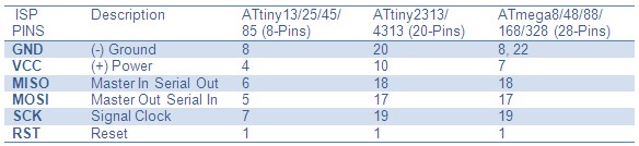
Now you are ready to use this ISP breakout board to program the Atmel Microcontroller based prototyping circuit. Make sure you always refer to the Atmel Microcontroller datasheet to correctly connect this ISP breakout board to your target microcontroller. The following table shows the ISP pins connection for some of the popular Atmel AVR Microcontrollers:
ISP_Breakout_03
The following picture show the Atmel ISP breakout board is used to program the Atmel AVR ATmega168 microcontroller based project on the breadboard:

This small ISP breakout board has been very useful to me in prototyping most of the Atmel microcontroller based circuit ever since. Now you could also share the same pleasure by building this little and handy Atmel ISP breakout board by yourself.

Transforming your AVR Microcontroller to the I2C or TWI Slave I/O Expander Project

The I2C bus (read as I squared C) is one of the most important embedded system serial bus interface first introduced by Philips in 1980; using just two lines called SCL (serial clock) and SDA (serial data) respectively make the I2C bus is a perfect choice to provide additional I/O capabilities to your microcontroller project without changing your microcontroller type and design in order to increase the I/O port pins.

Today there are plenty choices of I2C slave I/O port expander devices available on the market such as Philips PCF8574 and Microchip MCP23008 for addressable 8-bit general I/O ports which capable of handling I2C standard bus speed of 100Khz or fast speed mode of 400Khz; the Microchip MCP23008 even can handle up to 1.7Mhz bus speed. You could read more information about using I2C interface on my previous posted blog How to use I2C-bus on the Atmel AVR Microcontroller.
The usage of I2C slave devices is not merely for the I/O expander but it also use to expand your microcontroller capabilities as well as it’s functionalities such as the I2C real time clock from Maxim DS1307 (Using Maxim DS1307 Real Time Clock with Atmel AVR Microcontroller), Microchip TC1321 10-bit digital to analog converter (DAC), Microchip MCP2331 12-bit analog to digital converter (ADC), Microchip MCP9801 high accuracy temperature sensor and Microchip 24AA128 16KB EEPROM.
Although there are many types of sophisticated I2C slave devices available on the market, sometimes we need the I2C slave device which has the capabilities beyond that, something more powerful, more flexible and yet easy to be configured; the answer to this requirement is to use the microcontroller it self as the I2C slave device, that is why most of the midrange class microcontrollers have the I2C slave peripheral feature build inside it. This is what we are going to learn on this tutorial, where the principal we learn here could be applied to other microcontroller type as well.

The following is the list of hardware and software used in this tutorial:
  • AVRJazz Mega328 board from ermicro as the I2C master controller which base on the AVR ATmega328P microcontroller (board schema).
  • JazzMate MCP23008 board from ermicro which base on the Microchip MCP23008 8-bit I2C I/O expander.
  • AVRJazz Mega168 board from ermicro as the I2C slave device which base on the AVR ATmega168 microcontroller (board schema).
  • WinAVR for the GNU’s C compiler
  • Atmel AVR Studio 4 for the coding and debugging environment.
  • STK500 programmer from AVR Studio 4, using the AVRJazz Mega328 and AVRJazz Mega168 boards STK500 v2.0 bootloader facility.
The MCP23008 8-bit I/O Expander I2C slave
The Microchip MCP23008 will be a perfect model for our I2C slave device as it has the 3-bit configurable address (000 to 111) which provides up to 7 devices that could be attached to the I2C bus which give total of 56 ports. MCP23008 also come with 11 internal register to control its operation


As the I2C slave device, mean the MCP23008 will be the passive device that depends on the I2C master device to initiate the communication. On this tutorial I will use the AVRJazz Mega328 learning board as the I2C master controller; the following is the C code for the I2C master controller.
//***************************************************************************
//  File Name  : i2cmaster.c
//  Version  : 1.0
//  Description  : AVR I2C Bus Master
//  Author       : RWB
//  Target       : AVRJazz Mega328 Board
//  Compiler     : AVR-GCC 4.3.0; avr-libc 1.6.2 (WinAVR 20090313)
//  IDE          : Atmel AVR Studio 4.17
//  Programmer   : AVRJazz Mega328 STK500 v2.0 Bootloader
//               : AVR Visual Studio 4.17, STK500 programmer
//  Last Updated : 12 September 2009
//***************************************************************************
#include <avr/io.h>
#include <util/delay.h>
#include <compat/twi.h>
#define MAX_TRIES 50
#define MCP23008_ID    0x40  // MCP23008 Device Identifier
#define MCP23008_ADDR  0x0E  // MCP23008 Device Address
#define IODIR 0x00           // MCP23008 I/O Direction Register
#define GPIO  0x09           // MCP23008 General Purpose I/O Register
#define OLAT  0x0A           // MCP23008 Output Latch Register
#define I2C_START 0
#define I2C_DATA 1
#define I2C_DATA_ACK 2
#define I2C_STOP 3
#define ACK 1
#define NACK 0
#define DATASIZE 32
/* START I2C Routine */
unsigned char i2c_transmit(unsigned char type) {
  switch(type) {
     case I2C_START:    // Send Start Condition
       TWCR = (1 << TWINT) | (1 << TWSTA) | (1 << TWEN);
       break;
     case I2C_DATA:     // Send Data with No-Acknowledge
       TWCR = (1 << TWINT) | (1 << TWEN);
       break;
     case I2C_DATA_ACK: // Send Data with Acknowledge
       TWCR = (1 << TWEA) | (1 << TWINT) | (1 << TWEN);
       break;
     case I2C_STOP:     // Send Stop Condition
 TWCR = (1 << TWINT) | (1 << TWEN) | (1 << TWSTO);
 return 0;
  }
  // Wait for TWINT flag set on Register TWCR
  while (!(TWCR & (1 << TWINT)));
  // Return TWI Status Register, mask the prescaler bits (TWPS1,TWPS0)
  return (TWSR & 0xF8);
}
char i2c_start(unsigned int dev_id, unsigned int dev_addr, unsigned char rw_type)
{
  unsigned char n = 0;
  unsigned char twi_status;
  char r_val = -1;
i2c_retry:
  if (n++ >= MAX_TRIES) return r_val;
  // Transmit Start Condition
  twi_status=i2c_transmit(I2C_START);

  // Check the TWI Status
  if (twi_status == TW_MT_ARB_LOST) goto i2c_retry;
  if ((twi_status != TW_START) && (twi_status != TW_REP_START)) goto i2c_quit;
  // Send slave address (SLA_W)
  TWDR = (dev_id & 0xF0) | (dev_addr & 0x0E) | rw_type;
  // Transmit I2C Data
  twi_status=i2c_transmit(I2C_DATA);
  // Check the TWSR status
  if ((twi_status == TW_MT_SLA_NACK) || (twi_status == TW_MT_ARB_LOST)) goto i2c_retry;
  if (twi_status != TW_MT_SLA_ACK) goto i2c_quit;
  r_val=0;
i2c_quit:
  return r_val;
}
void i2c_stop(void)
{
  unsigned char twi_status;
  // Transmit I2C Data
  twi_status=i2c_transmit(I2C_STOP);
}
char i2c_write(char data)
{
  unsigned char twi_status;
  char r_val = -1;
  // Send the Data to I2C Bus
  TWDR = data;
  // Transmit I2C Data
  twi_status=i2c_transmit(I2C_DATA);
  // Check the TWSR status
  if (twi_status != TW_MT_DATA_ACK) goto i2c_quit;
  r_val=0;
i2c_quit:
  return r_val;
}
char i2c_read(char *data,char ack_type)
{
  unsigned char twi_status;
  char r_val = -1;               

  if (ack_type) {
    // Read I2C Data and Send Acknowledge
    twi_status=i2c_transmit(I2C_DATA_ACK);
    if (twi_status != TW_MR_DATA_ACK) goto i2c_quit;
  } else {
    // Read I2C Data and Send No Acknowledge
    twi_status=i2c_transmit(I2C_DATA);
    if (twi_status != TW_MR_DATA_NACK) goto i2c_quit;
  }
  // Get the Data
  *data=TWDR;
  r_val=0;
i2c_quit:
  return r_val;
}
void Write_MCP23008(unsigned char reg_addr,unsigned char data)
{
   // Start the I2C Write Transmission
   i2c_start(MCP23008_ID,MCP23008_ADDR,TW_WRITE);
   // Sending the Register Address
   i2c_write(reg_addr);
   // Write data to MCP23008 Register
   i2c_write(data);
   // Stop I2C Transmission
   i2c_stop();
}
unsigned char Read_MCP23008(unsigned char reg_addr)
{
   char data;
   // Start the I2C Write Transmission
   i2c_start(MCP23008_ID,MCP23008_ADDR,TW_WRITE);
   // Read data from MCP23008 Register Address
   i2c_write(reg_addr);
   // Stop I2C Transmission
   i2c_stop();

   // Re-Start the I2C Read Transmission
   i2c_start(MCP23008_ID,MCP23008_ADDR,TW_READ);
   i2c_read(&data,NACK);

   // Stop I2C Transmission
   i2c_stop();

   return data;
}
void i2c_init(void)
{
  // Initial ATMega328P TWI/I2C Peripheral
  TWSR = 0x00;         // Select Prescaler of 1
  // SCL frequency = 11059200 / (16 + 2 * 48 * 1) = 98.743 kHz
  TWBR = 0x30;        // 48 Decimal
}
int main(void)
{
  unsigned char ptr,data;
  unsigned int iDelay;    

  char led_pattern[DATASIZE]=
                        {0b00000001,
    0b00000011,
    0b00000110,
    0b00001100,
    0b00011001,
    0b00110011,
    0b01100110,
    0b11001100,
    0b10011000,
    0b00110000,
    0b01100000,
    0b11000000,
    0b10000000,
    0b00000000,
    0b00000000,
    0b00000000,
    0b10000000,
    0b11000000,
    0b01100000,
    0b00110000,
    0b10011000,
    0b11001100,
    0b01100110,
    0b00110011,
    0b00011001,
    0b00001100,
    0b00000110,
    0b00000011,
    0b00000001,
    0b00000000,
    0b00000000,
    0b00000000
   };         

  DDRD=0xFF;          // Set PORTD as Output
  PORTD=0x00;         // Set All PORTD to Low
   // Set ADCSRA Register on ATMega328
  ADCSRA = (1<<ADEN) | (1<<ADPS2) | (1<<ADPS1);
  // Set ADMUX Register on ATMega328
  ADMUX = 0x00;       // Use Left Justified, Select Channel 0
  // Initial Master I2C
  i2c_init();
  // Initial the MCP23008 GP0 to GP7 as Output
  Write_MCP23008(IODIR,0b00000000);
  Write_MCP23008(GPIO,0b00000000);    // Reset all the Output Port         

  // Loop Forever
  for (;;) {
    for(ptr=0;ptr < DATASIZE;ptr++) {
      // Start conversion by setting ADSC on ADCSRA Register
      ADCSRA |= (1<<ADSC);

      // wait until conversion complete ADSC=0 -> Complete
      while (ADCSRA & (1<<ADSC));
      // Get ADC the Result
      iDelay = ADCW;
      // Write to MCP23008 GPIO Register
      Write_MCP23008(GPIO,led_pattern[ptr]);

      // Read MCP23008 OLAT Register
      data=Read_MCP23008(OLAT);
      PORTD=data;                     // Write data to the ATMega328 Port-D

      _delay_ms(iDelay);           // Give some delay here
    }
  } 

  return 0;
}
/* EOF: i2cmaster.c */
Sending Data to the I2C Slave Device
In order to communicate with MCP23008 I2C slave device, the I2C master controller first has to send the START condition to take control of the I2C bus and continue with the I2C slave device 7-bit target address which consists of 4-bit MCP23008 I2C slave identification ID (0100) and 3-bit configurable address (000 to 111) follow by 1-bit of the read (TW_READ, logical “1“) or write (TW_WRITE, logical “0“) operation. After receiving its own 7-bit address then the I2C slave device will response to the I2C master controller by sending the acknowledge (ACK) signal.


Once the I2C master controller receive the I2C slave address acknowledge (ACK) signal, then it will start to send the requested register address to the I2C slave device. The I2C master controller then will continue to send the data to this register (GPIO) after the acknowledge (ACK) signal from I2C slave. Next the I2C master controller will close the communication by sending the STOP signal to the I2C slave.

The write operation to the MCP23008 is implemented in the C function Write_MCP23008() which accept two argument, register address and the data respectively:
void Write_MCP23008(unsigned char reg_addr,unsigned char data)
{
   // Start the I2C Write Transmission
   i2c_start(MCP23008_ID,MCP23008_ADDR,TW_WRITE);
   // Sending the Register Address
   i2c_write(reg_addr);
   // Write data to MCP23008 Register
   i2c_write(data);
   // Stop I2C Transmission
   i2c_stop();
}
Reading Data from the I2C Slave Device
Reading data from the MCP23008 I2C slave device required two phase, the first one is to tell the I2C slave device which register that we want to read; this required the write operation and then send the stop signal to the I2C slave device. The second phase is the actual read process; the I2C master than resend the START signal or known as restart signal again followed by I2C slave 7-bit address with read operation and it wait for acknowledge (ACK) signal to be replied by the I2C slave device. Once the I2C slave response with acknowledge (ACK) signal then the I2C master will enter the master receive mode and the I2C slave will continue to send the requested register data to the I2C master. Once the I2C master receive the data it will reply the no acknowledge (NACK) signal to the I2C slave device which tell the I2C slave that the read operation is finish and then the I2C master close the connection by sending the STOP signal.

The read operation from the MCP23008 is implemented in the C function Read_MCP23008() which accept the register address as its argument:
unsigned char Read_MCP23008(unsigned char reg_addr)
{
   char data;
   // Start the I2C Write Transmission
   i2c_start(MCP23008_ID,MCP23008_ADDR,TW_WRITE);
   // Read data from MCP23008 Register Address
   i2c_write(reg_addr);
   // Stop I2C Transmission
   i2c_stop();

   // Re-Start the I2C Read Transmission
   i2c_start(MCP23008_ID,MCP23008_ADDR,TW_READ);
   i2c_read(&data,NACK);

   // Stop I2C Transmission
   i2c_stop();

   return data;
}
Inside the I2C Master C Program
The I2C master program start with I/O port initialization and continue with the ADC initialization; we use the ATMega328P ADC peripheral to control the LED display delay. The delay value will be read from the user trimport on the AVRJazz Mega328 board attached to the PC0 (ADC0) port of the ATMega328P microcontroller. By adjusting this trimport we could adjust the LED display speed; for more information about using the ADC peripheral you could read my previous posted blog Analog to Digital Converter AVR C Programming
After initiate the TWI (Two Wire Interface) peripheral (Atmel’s implementation of the Philips I2C trademark interface) by calling the i2c_init() function, then we initiate the MCP23008 general I/O (GPIO) port for output. This could be done by assigning the 8-bit I/O direction register (IODIR) to 0×00. You could read more about using the Microchip MCP23008 as the I2C I/O expander in my previous posted blog Build Your Microcontroller Based PID Control Line Follower Robot.
// Initial the MCP23008 GP0 to GP7 as Output
Write_MCP23008(IODIR,0b00000000);
Write_MCP23008(GPIO,0b00000000);    // Reset all the Output Port
Inside the infinite for loop, we simply read the ADC result from the user trimport; then we write the LED pattern (led_pattern[]) to the MCP23008 GPIO register and then read the OLAT (Output Latch) register which represent the last value on the GPIO register; this give us an example of read operation from the MCP23008 I2C slave device. The 8-bit data read from OLAT register simply act as the output feedback data and we pass this data back to the ATMega328P PORTD.
for(ptr=0;ptr < DATASIZE;ptr++) {
  // Start conversion by setting ADSC on ADCSRA Register
  ADCSRA |= (1<<ADSC);

  // wait until conversion complete ADSC=0 -> Complete
  while (ADCSRA & (1<<ADSC));
  // Get ADC the Result
  iDelay = ADCW;
  // Write to MCP23008 GPIO Register
  Write_MCP23008(GPIO,led_pattern[ptr]);

  // Read MCP23008 OLAT Register
  data=Read_MCP23008(OLAT);
  PORTD=data;                    // Write data to the ATMega328P Port-D

  _delay_ms(iDelay);           // Give some delay here
}
Compile and Download the I2C Master Code to the AVRJazz Mega328 board
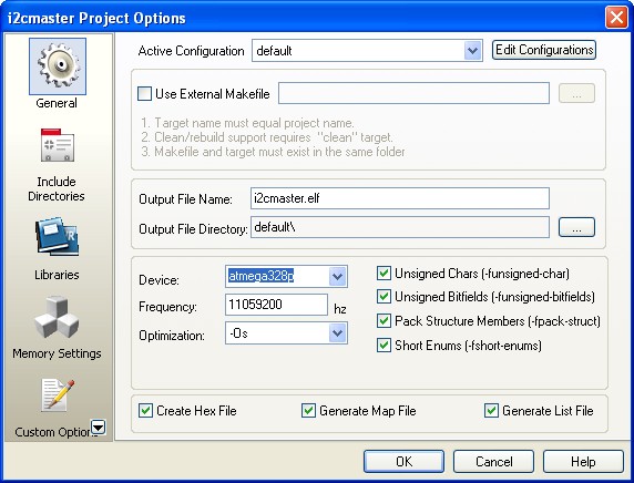
Before compiling the code, we have to make sure the AVR Studio 4 configuration is set properly by selecting menu project -> Configuration Option, the Configuration windows will appear as follow:

Make sure the Device selected is atmega328p and the Frequency use is 11059200 Hz.
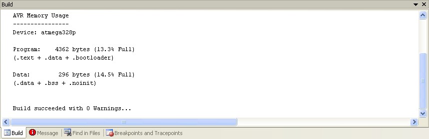
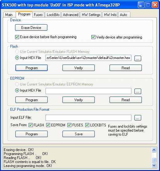
After compiling and simulating our code we are ready to down load the code using the AVRJazz Mega328 bootloader facility. The bootloader program is activated by pressing the user switch and reset switch at the same time; after releasing both switches, the 8 blue LED indicator will show that the bootloader program is activate and ready to received command from Atmel AVR Studio 4 STK500 program.


We choose the HEX file and press the Program Button to down load the code into the AVRJazz Mega328 board.

AVR ATMega168 microcontroller as the I2C Slave Device
On this last AVR I2C Slave tutorial we will transform the AVR ATMega168 to the I2C slave I/O device; as mention above we will use the MCP23008 I2C I/O expander as our I2C slave model. By emulating the MCP23008 chip using the AVR ATMega168 microcontroller we will have a good example of how to utilize the AVR ATMega168 TWI (I2C) slave peripheral feature and at the same time it will serve as a learning tools of how to program the microcontroller’s base I2C slave device.


The following is the AVR Mega168 microcontroller C code partial emulation of the MCP23008 I2C I/O Expander:
//***************************************************************************
//  File Name    : i2cslave.c
//  Version      : 1.0
//  Description  : I2C Slave AVR Microcontroller Interface
//                 MCP23008 Emulation GPIO = PORTD
//  Author       : RWB
//  Target       : AVRJazz Mega168 Learning Board
//  Compiler     : AVR-GCC 4.3.2; avr-libc 1.6.2 (WinAVR 20090313)
//  IDE          : Atmel AVR Studio 4.17
//  Programmer   : AVRJazz Mega168 STK500 v2.0 Bootloader
//               : AVR Visual Studio 4.17, STK500 programmer
//  Last Updated : 12 September 2009
//***************************************************************************
#include <avr/io.h>
#include <util/delay.h>
#include <compat/twi.h>
#include <avr/interrupt.h>
// MCP23008 8 Bit I/O Extention Simulation Address and Register Address
#define MCP23008_ADDR 0x4E
#define IODIR 0x00
#define GPIO 0x09
#define OLAT 0x0A
unsigned char regaddr;    // Store the MCP23008 Requested Register Address
unsigned char regdata;    // Store the MCP23008 Register Address Data
unsigned char olat_reg;   // Simulate MCP23008 OLAT Register
// Simulated OLAT alternative return pattern
#define MAX_PATTERN 7
unsigned char led_pattern[MAX_PATTERN]=
  {0b11110000,0b01111000,0b00111110,0b00011111,0b00111110,0b01111000,0b11110000};
// Simulated OLAT Return Mode: 0-Same as GPIO, 1-Use an alternative LED pattern above
volatile unsigned char olat_mode;  

void i2c_slave_action(unsigned char rw_status)
{
   static unsigned char iled=0;
   // rw_status: 0-Read, 1-Write
   switch(regaddr) {
     case IODIR:
       if (rw_status) {
  DDRD=~regdata;  // Write to IODIR - DDRD
       } else {
  regdata=DDRD;   // Read from IODIR - DDRD
       }   

       break;
     case GPIO:
       if (rw_status) {
  PORTD=regdata;  // Write to GPIO - PORTD
  olat_reg=regdata;
       } else {
  regdata=PIND;   // Read from GPIO - PORTD
       }
       break;
     case OLAT:
       if (rw_status == 0) {
  // Read from Simulated OLAT Register
  if (olat_mode) {
    regdata=led_pattern[iled++];
    if (iled >= MAX_PATTERN)
      iled = 0;
  } else {
    regdata=olat_reg;
  }
       }
   }
}
ISR(TWI_vect)
{
   static unsigned char i2c_state;
   unsigned char twi_status;
   // Disable Global Interrupt
   cli();
   // Get TWI Status Register, mask the prescaler bits (TWPS1,TWPS0)
   twi_status=TWSR & 0xF8;     

   switch(twi_status) {
     case TW_SR_SLA_ACK:      // 0x60: SLA+W received, ACK returned
       i2c_state=0;           // Start I2C State for Register Address required  

       TWCR |= (1<<TWINT);    // Clear TWINT Flag
       break;
     case TW_SR_DATA_ACK:     // 0x80: data received, ACK returned
       if (i2c_state == 0) {
         regaddr = TWDR;      // Save data to the register address
  i2c_state = 1;
       } else {
  regdata = TWDR;      // Save to the register data
  i2c_state = 2;
       }

       TWCR |= (1<<TWINT);    // Clear TWINT Flag
       break;
     case TW_SR_STOP:         // 0xA0: stop or repeated start condition received while selected
       if (i2c_state == 2) {
  i2c_slave_action(1); // Call Write I2C Action (rw_status = 1)
  i2c_state = 0;       // Reset I2C State
       }    

       TWCR |= (1<<TWINT);    // Clear TWINT Flag
       break;

     case TW_ST_SLA_ACK:      // 0xA8: SLA+R received, ACK returned
     case TW_ST_DATA_ACK:     // 0xB8: data transmitted, ACK received
       if (i2c_state == 1) {
  i2c_slave_action(0); // Call Read I2C Action (rw_status = 0)
  TWDR = regdata;      // Store data in TWDR register
  i2c_state = 0;       // Reset I2C State
       }       

       TWCR |= (1<<TWINT);    // Clear TWINT Flag
       break;
     case TW_ST_DATA_NACK:    // 0xC0: data transmitted, NACK received
     case TW_ST_LAST_DATA:    // 0xC8: last data byte transmitted, ACK received
     case TW_BUS_ERROR:       // 0x00: illegal start or stop condition
     default:
       TWCR |= (1<<TWINT);    // Clear TWINT Flag
       i2c_state = 0;         // Back to the Begining State
   }
   // Enable Global Interrupt
   sei();
}
int main(void)
{
  unsigned char press_tm;
  DDRB = 0xFE;      // Set PORTB: PB0=Input, Others as Output
  PORTB = 0x00;
  DDRD = 0xFF;      // Set PORTD to Output
  PORTD = 0x00;     // Set All PORTD to Low
  // Initial I2C Slave
  TWAR = MCP23008_ADDR & 0xFE; // Set I2C Address, Ignore I2C General Address 0x00
  TWDR = 0x00;                 // Default Initial Value
  // Start Slave Listening: Clear TWINT Flag, Enable ACK, Enable TWI, TWI Interrupt Enable
  TWCR = (1<<TWINT) | (1<<TWEA) | (1<<TWEN) | (1<<TWIE);
  // Enable Global Interrupt
  sei();

  // Initial Variable Used
  olat_reg=0;
  regaddr=0;
  regdata=0;
  olat_mode=0;
  press_tm=0;      

  for(;;) {
    if (bit_is_clear(PINB, PB0)) {          // if button is pressed
      _delay_us(100);                       // Wait for debouching
      if (bit_is_clear(PINB, PB0)) {
 press_tm++;
 if (press_tm > 100)
   olat_mode ^= 1;                 // Toggle the olat_mode
      }
    }
  }
  return 0;
}
/* EOF: i2cslave.c */
AVR ATMega168 I2C Slave
The AVR ATMega168 has build in I2C (TWI) peripheral both as master or slave, most of the AVR microcontroller families have these features and some of them (tiny families) shared the TWI pins (SCL and SDA) with other serial peripheral pins such as SPI (Serial Peripheral Interface) which usually called as the Universal Serial Interface (USI) (e.g. ATTiny2313, ATTiny24, ATTiny861).
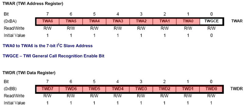
As you’ve learned from the MCP23008 I2C I/O expander above, that every I2C slave device must have the 7-bit address for its identification, the ATMega168 microcontroller implement this I2C slave address identification  in the TWAR (TWI Address) register (for more information please refer to the ATMega168 microcontroller datasheet).

By simply set the TWAR register to the MCP23008 identification address the I2C master controller will recognize the ATMega168 microcontroller as the MCP23008 chip, remember we will use the same I2C master program which drive the MCP23008 chip in this ATMega168 microcontroller I2C slave mode. The following is the C code that initiates this register:
// MCP23008 8 Bit I/O Extension Simulation Address and Register Address
#define MCP23008_ADDR 0x4E
#define IODIR 0x00
#define GPIO 0x09
#define OLAT 0x0A
...
...
// Initial I2C Slave
TWAR = MCP23008_ADDR & 0xFE; // Set I2C Address, Ignore I2C General Address 0x00
TWDR = 0x00;                 // Default Initial Value
Of course if you want to attach more ATMega168 microcontroller as the I2C slave on the same bus, you have to differentiate the address for each of them, theoretical you could attached up to 128 I2C devices on the same I2C bus. The 8-bit TWDR (TWI Data Register) register is responsible to receive and send the data to or from the ATMega168 microcontroller I2C slave peripheral. Therefore by simply reading this register or writing to this register we could receive or sending the data through the I2C bus.
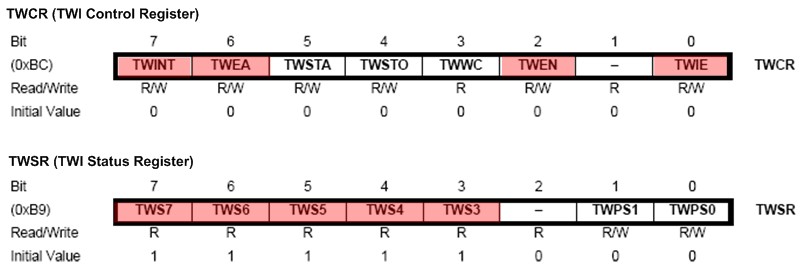
The last two important register for the ATMega168 microcontroller I2C slave peripheral operation are TWCR (TWI Control Register) and TWSR (TWI Status Register).

To operate the ATMega168 microcontroller in I2C slave mode, first we have to enable the TWI peripheral by setting the TWEN (TWI Enable) bit of the TWCR register to logical “1” and to enable the acknowledge signal for the I2C master/slave handshake we set the TWEA (TWI Enable Acknowledge) bit of the TWCR register to logical “1“.
For the efficient reason on this tutorial I implement the interrupt service routine for the I2C slave operation, this could be done by setting the TWIE (TWI Enable Interrupt) bit of TWCR register to logical “1” and enable the global interrupt bit (I) on the SREG register by calling the sei() macro definition, the AVR-GCC implementation of the AVR “sei” assembly command. The following C code shows how to set this TWCR register:
...
// Start Slave Listening: Clear TWINT Flag, Enable ACK, Enable TWI, TWI Interrupt Enable
TWCR = (1<<TWINT) | (1<<TWEA) | (1<<TWEN) | (1<<TWIE);
// Enable Global Interrupt
sei();
Every time the I2C master communicate with the I2C slave, the TWSR register will be updated with valid status code and set the TWINT (TWI Interrupt) flag to logical “0“, the valid status read from the TWSR register will be used by software implementation to decide the action required to complete the I2C master/slave communication. The TWINT flag bit has to be reset by software before we start to the next I2C master/slave handshake. The ISR(TWI_vect) and i2c_slave_action() are the C code that implement the AVR ATMega168 microcontroller I2C slave peripheral.
Actually there is one more register left for the AVR ATMega168 microcontroller I2C slave peripheral operation named TWAMR (TWI Address Mask Register) which is use to disable the corresponding bit in the TWAR register when set to logical “1“. This could be used to change the I2C slave address identification without changing the TWAR register content.
To make the program more interesting and at the same time demonstrating of how we could implement more advance application to the microcontroller’s based I2C slave device; I decided to use the AVRJazz Mega168 user switch attached to the ATMega168 PB0 to manipulate the simulated MCP23008 OLAT register data in the i2c_slave_action() function.
...
...
// Simulated OLAT alternative return pattern
#define MAX_PATTERN 7
unsigned char led_pattern[MAX_PATTERN]=
  {0b11110000,0b01111000,0b00111110,0b00011111,0b00111110,0b01111000,0b11110000};
// Simulated OLAT Return Mode: 0-Same as GPIO, 1-Use an alternative LED pattern above
volatile unsigned char olat_mode;
...
...
 case GPIO:
   if (rw_status) {
     PORTD=regdata;  // Write to GPIO - PORTD
     olat_reg=regdata;
   } else {
     regdata=PIND;   // Read from GPIO - PORTD
   }
   break;
  case OLAT:
    if (rw_status == 0) {
      // Read from Simulated OLAT Register
      if (olat_mode) {
  regdata=led_pattern[iled++];
        if (iled >= MAX_PATTERN)
   iled = 0;
      } else {
  regdata=olat_reg;
      }
    }
...
As you notice from the C code above if the olat_mode variable equal to 1, then the MCP23008 simulated OLAT register will return different LED pattern that is taken from the led_pattern[] variables. The olat_mode variable is controlled by pressing the AVRJazz Mega168 board user switch read from the ATMega168 PB0 port status inside the infinite for loop.
if (bit_is_clear(PINB, PB0)) {          // if button is pressed
  _delay_us(100);                       // Wait for debouching
  if (bit_is_clear(PINB, PB0)) {
    press_tm++;
    if (press_tm > 100)
      olat_mode ^= 1;                  // Toggle the olat_mode
  }
}
Compile and Download the I2C Master Code to the AVRJazz Mega168 board
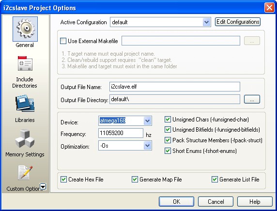
Before compiling the code, we have to make sure the AVR Studio 4 configuration is set properly by selecting menu project -> Configuration Option, the Configuration windows will appear as follow:

Make sure the Device selected is atmega168 and the Frequency use is 11059200 Hz.
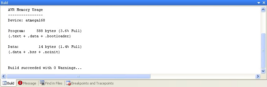
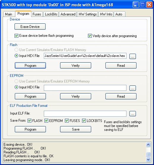
After compiling and simulating our code we are ready to down load the code using the AVRJazz Mega168 bootloader facility. The bootloader program is activated by pressing the user switch and reset switch at the same time; after releasing both switches, the 8 blue LED indicator will show that the bootloader program is activate and ready to received command from Atmel AVR Studio 4 STK500 program.


We choose the HEX file and press the Program Button to down load the code into the AVRJazz Mega168 board. Now you could enjoy the following video showing all the experiments we’ve done in this I2C slave tutorial:
The Final Though
The usage of microcontroller’s based I2C slave device opening the enormous chances to build more advance embedded system application, where you could attached multiple microcontroller and freeing your master microcontroller (I2C master) to perform the main logic for your application, while the co-microcontroller (I2C slave) could be programmed to do just a specific task such as advanced PWM motor controller, multiple servo controller (robotics arm and leg), LCD controller (driving LCD display through I2C), smart sensors and many more.
Last what I like the most is, you could mix and match the microcontroller brand and type such as Atmel AVR families and Microchip PIC families, where you could take advantage of the features and strength of both microcontrollers to support your embedded system application.

Building the I2C Smart DC Motor Controller with Atmel AVR Microcontroller – Part 1

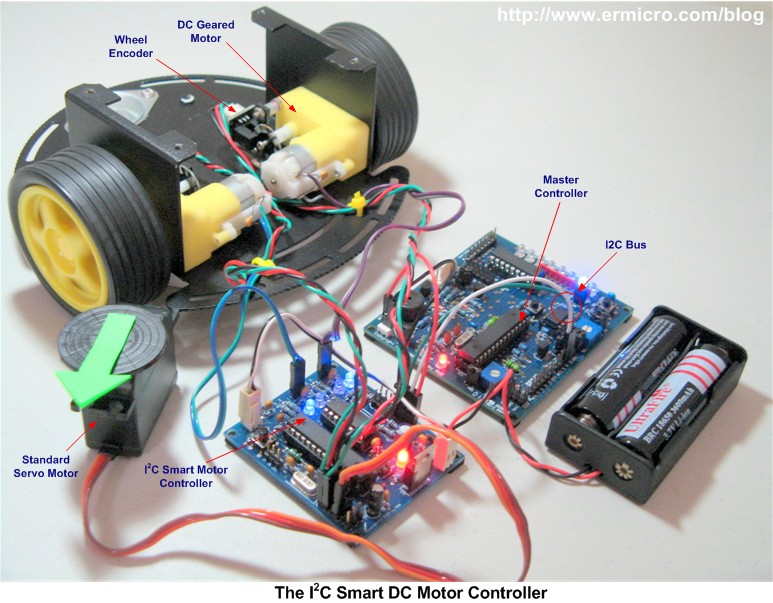
The idea of building my own I2C (read as I square C) smart DC motor controller is came to me when I was learning and playing together with my son on his LEGO® MINDSTORM® NXT 2.0 about a year ago. The NXT sophisticated controller also called NXT Intelligent Brick is powered by Atmel 32-bit ARM7 AT91SAM7S256 microcontroller and communicating with Atmel 8-bit AVR ATmega48 acting as a co-microcontroller using I2C protocol. This NXT co-microcontroller main function is to help handle some of the NXT I/O special task i.e. power management, reading buttons, analog’s input sensors and control to the motors. The following picture shows my version of the I2C smart DC motor controller which is power by Atmel 8-bit AVR ATmega168 microcontroller:


The advantage of separating this special I/O task to the co-microcontroller is to release the main microcontroller from the hungry resources task such as generating the required Pulse Width Modulation (PWM) to the motor and reading the analog input, therefore the main microcontroller could be used to do other important task. This I2C smart motor controller which has these following features:
  • Communicate with a standard I2C protocol to the any smart controller (e.g. microcontroller based board or microprocessor based board) that supports I2C protocol.
  • Driving two DC geared Motors simultaneously which maximum current up to 1 A, maximum voltage of 20 volts
  • Separate PWM for each motor for precision motor steering
  • Build in steering routine such e.g. forward/backward, turn left/right, rotate left/right, and arc left/right
  • Support unlimited, timed (in second), rotation (with wheel encoder), and degree (with wheel encoder) wheel movement
  • One channel precision 5 volt Servo Motor Driver
  • Two Interrupt input channel for wheel encoder
  • One 10-bit analog input channel
  • TTL UART communication, implemented for debugging purpose
I will split this project into 3 articles (part 1 to 3) and as we move to implement more complex features, the firmware will be slightly modified to support the additional features, and finally we will use a different type of master controller board to experiment with this I2C smart DC motor controller as shown in this following picture:

This I2C smart DC motor controller project also serve as a basic knowledge required to any microcontroller enthusiast or hobbyists to start their own embedded system application design. Ok let’s take a look at all the electronic components and software required to develop this project:
  1. Resistors: 10K Ohm (6), 330 Ohm (1), 1K Ohm (4)
  2. Capacitors: 0.1uF (7), 0.01uF (1), 22pF (2), 100uF/25v (1), 10uF/25v (1)
  3. Inductor: 100uH (1)
  4. Crystal: 16 MHz (1) used for external clock
  5. Diode: 1N5817 (1)
  6. LED: 3mm blue (4), 3 mm red (1)
  7. One 5 Volt Regulator IC LM7805
  8. One Atmel AVR ATmega168 Microcontroller
  9. One L293D Push Pull Four Channel Motor Driver
  10. One Tactical Switch
  11. One standard size Breadboard
  12. Adequate jumper cables for bread boarding
  13. One USB to UART converter for debugging
  14. Atmel AVR Studio 6.0 for coding and debugging environment
  15. Atmel AVR Programmer such as Atmel mkII programmer
  16. 5 Alkaline AA battery (7.5 volt) or two 18650 3.7volt Rechargeable Lithium battery (7.4 volt), or any adequate 7.5 volt regulated DC power source.
  17. Atmel AVR ATmega168 and L293D Datasheet
  18. The complete electronic schematic file (PDF) for this project
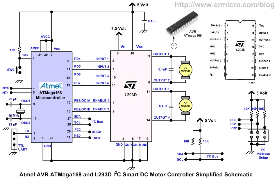
The following is a simplified version of the I2C smart DC motor controller electronic schematic used in this project:
The AVR ATmega168 as the I2C Slave
The I2C bus use only 2 bidirectional data lines called SDA (serial data) and SCL (serial clock) for communicating between the main microcontroller called “Master” and co-microcontroller called “Slave”. The I2C protocol specification can support up to 128 slave devices attached to the same bus which is one of its the main advantages.

The master I2C controller is responsible to initiate any communication between the I2C master device and the I2C slave device. Each of these I2C slave devices has their own 7-bit individual address which consists of fixed 4-bit device identification and configurable 3-bit physical address. These individual slave addresses allow the master controller to communicate to each of the slave devices attached to the I2C bus. You could read more about the I2C in these articles “How to use I2C-bus on the Atmel AVR Microcontroller” and “Transforming your AVR Microcontroller to the I2C (TWI) Slave I/O Expander Devices Project”.
In the first part, I will implement the AVR ATmega168 microcontroller as the I2C slave with a simple speed and steering motor controller. Therefore on top of I2C protocol I’ve used a simple data write and read rules (protocol), so the master controller could easily communicate with the I2C smart DC Motor controlling using this following I2C data communication format:

The I2C master controller first will send the “start” condition to the I2C bus; this will trigger the attention to the entire I2C slave devices attached to the same bus. Next the I2C master controller will send the particular I2C slave address with write instruction, in our case the I2C smart DC motor controller has the 4-bit fixed address of “1000” and configurable 3-bit address of “111”, therefore the I2C slave device will send the “acknowledge” to the I2C master controlled. Next the I2C master will send the first 8-bit data (i.e. register address) and the second 8-bit data (i.e. register data) before sending the “stop” condition.
By interpreting the appropriate register address and register data send by the I2C master controller, the I2C slave device could be programmed to response to any specific request needed as shown in this following picture:

The following is the first version of our firmware which implements these features written in AVR GCC language.
//***************************************************************************
//  File Name    : i2cmcont.c
//  Version      : 0.8
//  Description  : I2C Smart Motor Controller Firmware version 0.8
//  Author       : RWB
//  Target       : Atmel AVR ATmega168 Microcontroller
//  Compiler     : AVR_8_bit_GNU_Toolchain_3.4.0_663
//  IDE          : Atmel AVR Studio 6.0
//  Programmer   : Atmel AVRISP mkII 
//               : Atmel AVR Studio 6.0
//  Last Updated : 12 February 2013
//***************************************************************************
#define F_CPU 16000000UL   // Used 16MHz 

// I2C Motor Control Debugging Mode, 0-Debug Off, 1-Debug On
#define I2C_MCTL_DEBUG 0

#include <avr/io.h>
#include <util/delay.h>
#include <compat/twi.h>
#include <avr/interrupt.h>

#if I2C_MCTL_DEBUG 
#include <stdio.h>

#define BAUD_RATE 19200
#endif

// I2C Motor Address and Register Address
#define I2C_MCTL_ADDR 0x4E
#define I2C_MCTL_ID 0x40

// MCONTL - Motor Control Register Address
// BIT 2,1,0 - Steering: 000-Stop, 001-Forward, 010-Backward, 011-Break
//                       100-Turn Left, 101-Turn Right, 110-Rotate Left,
//                    111-Rotate Right
// BIT 4,3 - Duration: 00-Unlimited, 01-Reserve, 10-Reserve, 11-Reserve
// BIT 5-7 - Reverse
// 
#define MCONTL 0x00
volatile uint8_t motor_contl = 0x00; // Motor Control Data Register 

// MECONT - Extended Motor Control Register Address
// BIT 0-7 - Reserve
#define MECONT 0x01
volatile uint8_t motor_econt = 0x00; // Extended Motor Control Data Register 

#define MDURA 0x02
// BIT 0-7 - Reserve
volatile uint8_t motor_dur = 0x00;   // Motor Duration 8-Bit Data Register

#define MSTEER 0x03
// BIT 0-7 - Reserve
volatile uint8_t motor_steer = 0x00; // Motor Steer Data Register 

// MPOWER - Motor Power Register Address
// Value: 0 to 100
// This Register will automatically write to MPWMA and MPWMB registers
#define MPOWER 0x04
volatile uint8_t motor_pwr = 100;   // Motor A/B Power Data Register 

// MPWMA - Motor A PWM Register Address
// Value: 0 to 100
#define MPWMA 0x05
volatile uint8_t pwm_a = 100;       // Motor A PWM Data Register 

// MPWMB - Motor B PWM Register Address
// Value: 0 to 100
#define MPWMB 0x06
volatile uint8_t pwm_b = 100;       // Motor B PWM Data Register 

// Define The I2C Motor Differential Steering
#define FULL_STOP     0
#define MOVE_FORWARD  1
#define MOVE_BACKWARD 2
#define FULL_BREAK    3
#define TURN_LEFT     4
#define TURN_RIGHT    5
#define ROTATE_LEFT   6
#define ROTATE_RIGHT  7

// I2C Motor Controller Register variables
volatile uint8_t regaddr,regdata;  

// Motor PWM variables
volatile uint16_t pwm_top=4000;
volatile uint16_t pwm_duty=40;

#if I2C_MCTL_DEBUG 
// UART Functions
void uart_init(void)
{
  UBRR0H = (((F_CPU/BAUD_RATE)/16)-1)>>8;    // set baud rate
  UBRR0L = (((F_CPU/BAUD_RATE)/16)-1);
  UCSR0B = (1<<RXEN0)|(1<<TXEN0);         // enable Rx & Tx
  UCSR0C=  (1<<UCSZ01)|(1<<UCSZ00);              // config USART; 8N1
}

void uart_flush(void)
{
  unsigned char dummy;

  while (UCSR0A & (1<<RXC0)) dummy = UDR0;
}

int uart_putch(char ch,FILE *stream)
{    
   if (ch == '\n')
    uart_putch('\r', stream);

   while (!(UCSR0A & (1<<UDRE0)));
   UDR0=ch;

   return 0;
}

int uart_getch(FILE *stream)
{
   unsigned char ch;

   while (!(UCSR0A & (1<<RXC0)));
   ch=UDR0;  

   // Echo the Output Back to terminal 
   uart_putch(ch,stream);       

   return ch;
}
#endif

void MotorPWM(uint8_t msel)
{   
  if (msel == 0x00) {    
    OCR1A=pwm_top - (pwm_duty * pwm_a); // Set the Motor A Duty Cycle               
  } else {
    OCR1B=pwm_top - (pwm_duty * pwm_b); // Set the Motor B Duty Cycle                
  }
}

void MotorPower(void)
{  
  pwm_a=motor_pwr;
  MotorPWM(0);        // Set Motor A PWM
  pwm_b=motor_pwr;
  MotorPWM(1);        // Set Motor B PWM  
}

void MotorDirection(uint8_t msteer)
{  
#if I2C_MCTL_DEBUG  
  printf("Motor Direction: %d\n",msteer);  
#endif  
  switch(msteer) {
    case FULL_STOP:      
      PORTD &= ~(1 << PD4); PORTD &= ~(1 << PD5); // Motor A Stop 
      PORTD &= ~(1 << PD6); PORTD &= ~(1 << PD7); // Motor B Stop
      break;
    case MOVE_FORWARD:
      PORTD &= ~(1 << PD4); PORTD |= (1 << PD5);  // Motor A On Forward
      PORTD &= ~(1 << PD6); PORTD |= (1 << PD7);  // Motor B On Forward            
      break;
    case MOVE_BACKWARD:
      PORTD |= (1 << PD4); PORTD &= ~(1 << PD5);  // Motor A On Reverse
      PORTD |= (1 << PD6); PORTD &= ~(1 << PD7);  // Motor A On Reverse      
      break;
    case FULL_BREAK:      
      PORTD |= (1 << PD4); PORTD |= (1 << PD5);   // Motor A Break 
      PORTD |= (1 << PD6); PORTD |= (1 << PD7);   // Motor B Break
      break;    
    case TURN_LEFT:
      MotorPower();
      PORTD &= ~(1 << PD4); PORTD |= (1 << PD5);  // Motor A On Forward
      PORTD &= ~(1 << PD6); PORTD &= ~(1 << PD7); // Motor B Off      
      break;
    case TURN_RIGHT:
      MotorPower();
      PORTD &= ~(1 << PD4); PORTD &= ~(1 << PD5); // Motor A Off
      PORTD &= ~(1 << PD6); PORTD |= (1 << PD7);  // Motor B On Forward            
      break;    
    case ROTATE_LEFT:
      MotorPower();
      PORTD &= ~(1 << PD4); PORTD |= (1 << PD5);  // Motor A On Forward
      PORTD |= (1 << PD6); PORTD &= ~(1 << PD7);  // Motor B On Reverse      
      break;
    case ROTATE_RIGHT:
      MotorPower();
      PORTD |= (1 << PD4); PORTD &= ~(1 << PD5);  // Motor A On Reverse
      PORTD &= ~(1 << PD6); PORTD |= (1 << PD7);  // Motor B On Forward      
      break;   
  }  
}

void ControlAction(uint8_t rw_status)
{    
#if I2C_MCTL_DEBUG  
  printf("Register Address: %x\n",regaddr);
  printf("Register Data: %x\n",regdata);
#endif     
  // rw_status: 0-Read, 1-Write
  switch(regaddr) {      
    case MCONTL:                         
      if (rw_status) {
        motor_contl=regdata;  // Write to Motor Control Register                            

        // Set Motor Direction
        MotorDirection((motor_contl & 0x07));    
      } else {
        regdata=motor_contl;  // Read from Motor Control Register                 
      }                                 
      break;
    case MECONT:
      if (rw_status) {
        motor_econt=regdata;  // Write to Extended Motor Control Register 
      } else {
        regdata=motor_econt;  // Read from Extended Motor Control Register 
      }
      break;       
    case MDURA:
      if (rw_status) {
        motor_dur=regdata;    // Write to Motor Duration Register          
      } else {
        regdata=motor_dur;    // Read from Motor Duration Register  
      }
      break;    
    case MSTEER:                    
      if (rw_status) {
        motor_steer=regdata;  // Write to Motor Steering register        
      } else {
        regdata=motor_steer;  // Read from Motor Steering register
      }
      break;
    case MPOWER:                    
      if (rw_status) {
        motor_pwr=regdata;    // Write to Motor Power register
        if (motor_pwr > 100) motor_pwr = 100;
        MotorPower();         // Set Motor Power to Motor A and Motor B
      } else {
        regdata=motor_pwr;    // Read from Motor Power register
      }
      break;     
    case MPWMA:                         
      if (rw_status) {
        pwm_a=regdata;       // Write to PWMA register     
        if (pwm_a > 100) pwm_a = 100;
        MotorPWM(0);         // Set PWM On Motor A         
      } else {
        regdata=pwm_a;       // Read from PWMA register    
      }             
      break;
    case MPWMB:                         
      if (rw_status) {
        pwm_b=regdata;       // Write to PWMB register
        if (pwm_b > 100) pwm_b = 100;
        MotorPWM(1);         // Set PWM On Motor B
      } else {
        regdata=pwm_b;       // Read from PWMB register   
      }                          
      break;       
  } 
}

ISR(TWI_vect)
{     
   static uint8_t i2c_state;    
   // Disable Global Interrupt
   cli(); 

   // Get TWI Status Register, mask the prescaler bits (TWPS1,TWPS0)    
   switch(TWSR & 0xF8) {    
     case TW_SR_SLA_ACK:      // 0x60: SLA+W received, ACK returned                 
       i2c_state=0;           // Start I2C State for Register Address required     

       TWCR |= (1<<TWINT);    // Clear TWINT Flag      
       break;

     case TW_SR_DATA_ACK:     // 0x80: data received, ACK returned       
    if (i2c_state == 0) {                 
         regaddr = TWDR;      // Save data to the register address         
     i2c_state = 1;             
       } else {                          
     regdata = TWDR;      // Save to the register data             
     i2c_state = 2;            
       }

       TWCR |= (1<<TWINT);    // Clear TWINT Flag          
       break;

     case TW_SR_STOP:   // 0xA0: stop or repeated start condition received while selected            
       if (i2c_state == 2) {            
      ControlAction(1);    // Call Write I2C Action (rw_status = 1)          
      i2c_state = 0;    // Reset I2C State           
    }       

    TWCR |= (1<<TWINT);    // Clear TWINT Flag         
    break;

     case TW_ST_SLA_ACK:      // 0xA8: SLA+R received, ACK returned            
     case TW_ST_DATA_ACK:     // 0xB8: data transmitted, ACK received      
    if (i2c_state == 1) {          
      ControlAction(0);    // Call Read I2C Action (rw_status = 0)

     TWDR = regdata;      // Store data in TWDR register
     i2c_state = 0;    // Reset I2C State                     
       }             

       TWCR |= (1<<TWINT);     // Clear TWINT Flag
       break;       

     case TW_ST_DATA_NACK:    // 0xC0: data transmitted, NACK received       
     case TW_ST_LAST_DATA:      // 0xC8: last data byte transmitted, ACK received 
     case TW_BUS_ERROR:       // 0x00: illegal start or stop condition
     default:                           
    TWCR |= (1<<TWINT);    // Clear TWINT Flag       
    i2c_state = 0;         // Back to the Begining State       
   }   

   // Enable Global Interrupt
   sei();  
}

#if I2C_MCTL_DEBUG 
// Assign I/O stream to UART 
FILE uart_str = FDEV_SETUP_STREAM(uart_putch, uart_getch, _FDEV_SETUP_RW);
#endif

int main(void)
{        
  uint8_t i2c_address;   

  DDRB = 0xFF;      // Set PORTB as Output
  PORTB = 0x00;     // Reset PORTB Output
  DDRC = 0x00;      // Set PORTC as Input
  PORTC = 0x07;     // Activate Pul-up on PORTC: 0,1,3
  DDRD = 0xF0;      // Set PORTD: 0,1,2,3 as input and PORTD 4,5,6,7 as Output  
  PORTD = 0x0F;     // Set All PORTD 0,1,2,3 High and PORTD 4,5,6,7 to Low      

#if I2C_MCTL_DEBUG 
  // Define Output/Input Stream  
  stdout = stdin = &uart_str;      

  // Initial UART Peripheral 
  uart_init();           
#endif 

  // Motor PWM using TIMER1
  // Initial the 16-bit TIMER1 PWM, Phase and Frequency Correct
  // Set OC1A and OC1B when up counting, Clear OC1A and OC1B when down counting
  TCCR1A = (1<<COM1A1)|(1<<COM1A0)|(1<<COM1B1)|(1<<COM1B0);   

  // TCNT1 Counter Increment Freq: 1 / (Fclk/ (2 x 1 x pwm_top) 
  //                         Freq = 1 / (16000000/8000) = 2000 Hertz
  // PWM, Phase and Frequency Correct, pwm_top = ICR1 = 4000, Prescaler: 1
  TCCR1B = (1<<WGM13)|(1<<CS10);      

  // Set the TIMER1 PWM Top Value ICR1 and OCR1A/OCR1B  
  ICR1=pwm_top;  // Used default 2000 Hz  
  OCR1A=pwm_top - (pwm_duty * pwm_a); // Set the Motor A Duty Cycle                 
  OCR1B=pwm_top - (pwm_duty * pwm_b); // Set the Motor B Duty Cycle          

  // Now read the I2C Address from PC0, PC1, and PC2  
  i2c_address=I2C_MCTL_ID | ((PINC & 0x07) << 1);

  // Initial I2C Slave
  TWAR = i2c_address & 0xFE;   // Set I2C Address, Ignore I2C General Address 0x00   
  TWDR = 0x00;                 // Default Initial Value

  // Start Slave Listening: Clear TWINT Flag, Enable ACK, Enable TWI, TWI Interrupt Enable
  TWCR = (1<<TWINT) | (1<<TWEA) | (1<<TWEN) | (1<<TWIE);    

  // Enable Global Interrupt
  sei();    

  // Assigned Default I2C Motor Control Register Value  
  MotorPower();          // Set Motor Power to Motor A and Motor B     

  for(;;) {            
    _delay_us(50);      // Put 50 us delay here        
  }         
  return 0;
}              

// EOF: i2cmcont.c, version 0.8
The I2C configurable address is determined by the logical input status of PC0, PC1, and PC2 on PORTC witch if configured as input port, next these 3 bits value is combined with the device 4-bits fix ID value of “1000” (I2C_MCTL_ID) and be assigned to the Two Wire Interface Address Register (TWAR, Two Wire Interface is the name given by Atmel for the Philips I2C interface) as shown on this following C code:
// Now read the I2C Address from PC0, PC1, and PC2
i2c_address=I2C_MCTL_ID | ((PINC & 0x07) << 1);
// Initial I2C Slave
TWAR = i2c_address & 0xFE; // Set I2C Address, Ignore I2C General Address 0x00
TWDR = 0x00; // Default Initial Value
Next we enable the I2C acknowledgement of the device’s own slave address by setting the TWEA bit and TWSTA bit and TWSTO bit must be written to zero on TWCR (Two Wire Interface Control Register) and activate the interrupt as shown in this following C Code:
// Start Slave Listening: Clear TWINT Flag, Enable ACK, Enable TWI, TWI Interrupt Enable
TWCR = (1<<TWINT) | (1<<TWEA) | (1<<TWEN) | (1<<TWIE);
// Enable Global Interrupt
sei();
Now all the I2C master request to the I2C slave will be handled by interrupt in the ISR(TWI_vect) function where the request to the I2C slave and response from the I2C slave will be read or assigned to the TWDR (Two Wire Interface Data Register). Therefore by interpreting the “predetermined” data (protocols) send from the I2C master, the I2C slave device could easily be programmed to behave as instructed e.g. turn on the DC motor, steering the wheel, controlling the motor speed, etc as implemented in the ControlAction() function.
The Motor Steering and Power
The motor steering is controlled by the SGS L293D four channel motor drivers which capable of driving 600mA continue current on each channel. The L293D chip has equipped with a flying diode on each channel which simplified the overall electronic schematic design. By configuring two of the L293D channels as the H-Bridge circuit driver to each of the DC Motor, we could easily control the two DC motor rotation direction and speed as shown in this following picture.

The L293D chip IN1 to IN4 input terminal is connected to the AVR ATmega168P microcontroller PD4 to PD7 output port, while the L293D four channel ENABLE1 and ENABLE2 input are connected to the AVR ATmega168P microcontroller 16-bit TIMER2 PWM output channel OC1A and OC1B.

The DC motor differential steering is controlled by applying the correct output logic (see the L293D truth table above) to the PD4 to PD7 output on PORTD which is implemented in the MotorDirection() function.
By supplying the PWM (Pulse Width Modulation) signal on each of the L293D chip ENABLE input we could control the power on each DC Motor. The AVR ATmega168 microcontroller 16-bit TIMER1 is choosed as the DC motor PWM source and is configured as the Phase and Frequency Correct PWM mode, we choose this mode as later on we will implement a flexible configurable PWM frequency in the I2C smart DC motor Controller firmware. You could read more about AVR PWM in these articles “Introduction to AVR Microcontroller Pulse Width Modulation (PWM)”, “AVR Twinkle Twinkle Using PWM Project” and “Working with Atmel AVR Microcontroller Basic Pulse Width Modulation (PWM) Peripheral”.
The TIMER1 Phase and Frequency Correct PWM mode used a dual slope counter operation in order to generate the PWM signal. First the 16-bit TIMER1 counter TCNT1 will count up, when the TCNT1 reach the OCR1A or OCR1B (Output Compare Register) value then the TIMER1 pheripheral will set the OC1A or OC1B output to a logical one. When the TCNT1 reach its maximum value (TOP) set in ICR1 (Input Capture Register) value, then the TCNT1 will start to count down, when it reach the OCR1A or OCR1B value the TIMER1 pheripheral will reset the OC1A or OC1B output to a logical zero as shown in this following picture.

The TIMER1 Phase and Frequency Correct PWM mode is initialized in this following C code:
// Motor PWM using TIMER1
// Initial the 16-bit TIMER1 PWM, Phase and Frequency Correct
// Set OC1A and OC1B when up counting, Clear OC1A and OC1B when down counting
TCCR1A = (1<<COM1A1)|(1<<COM1A0)|(1<<COM1B1)|(1<<COM1B0);   

// TCNT1 Counter Increment Freq: 1 / (Fclk/ (2 x 1 x pwm_top) 
//                         Freq = 1 / (16000000/8000) = 2000 Hertz
// PWM, Phase and Frequency Correct, pwm_top = ICR1 = 4000, Prescaler: 1
TCCR1B = (1<<WGM13)|(1<<CS10);      

// Set the TIMER1 PWM Top Value ICR1 and OCR1A/OCR1B  
ICR1=pwm_top;  // Used default 2000 Hz  
OCR1A=pwm_top - (pwm_duty * pwm_a); // Set the Motor A Duty Cycle                 
OCR1B=pwm_top - (pwm_duty * pwm_b); // Set the Motor B Duty Cycle
The PWM frequency is controled by the TCNT1 maximum counter value or ICR1 register value and could be calculated using this following formula:
PWM Frequency = Freq Clock / (2 x n x TOP)
With the frequency clock of 16.000.000 Hz, prescaler (n) of 1 and TOP value of 4000 (pwm_top variable), the PWM frequency is 2000 Hz.
The PWM duty cycle is controlled by the OCR1A and OCR1B register value. Therefore by changing the OCR1A and OCR1B value we could easily change each of the DC motor speed connected to AVR ATmega168 microcontroller OC1A (PB1) and OC1B (PB2) output port. The duty cycle could be calculated using this following formula:
OCR1A = pwm_top – (pwm_duty x pwm_a)
OCR1B = pwm_top – (pwm_duty x pwm_b)
Where pwm_top and pwm_duty variables are fixed value of 4000 and 40, while the pwm_a or pwm_b variable value represent the PWM output duty cycle from 0 to 100, therefore by setting the pwm_a or pwm_b to 100 the OCR1A or OCR1B value is 0 (100% PWM duty cycle) or when pwm_a or pwm_b is set to 0 the OCR1A or OCR1B value is 4000 (0% PWM duty cycle). The DC Motor speed control is implemented in MotorPower() and MotorPWM() functions.
One of the important feature implemented in this project is the runtime debugging which is implemented using the Atmel AVR ATmega168 microcontroller UART peripheral. This runtime debugging will help us to capture and examine program variables value on the terminal such as window Hyperterminal or PuTTY program (i.e. baud rate: 19200, data bit: 8, and stop bit: 1) while we run the code. In order to enable this debugging feature you could simply change the I2C_MCTL_DEBUG definition from 0 to 1 and connect the AVR UART port RXD (PD0) and TXD (PD1) to the UART to USB or UART to RS232 adapter to your personal computer.
Testing the I2C Smart DC Motor Controller Firmware
In order to test the first version of the I2C Smart DC Motor Controller firmware, I will use the Atmel AVR ATmega328P microcontroller with the AVRJazz 28PIN board. Where we simply connect the AVR ATmega328P TWI (two wire inteface) port SDA (PC4) and SCL (PC5) to the SDA and SCL port of the I2C Smart DC Motor Controler. The following is a complete C code where the AVR ATmega328P microcontroller is configured as the I2C master controller.
//***************************************************************************
//  File Name    : i2cmdemo.c
//  Version      : 0.8
//  Description  : I2C Master Demo for I2C DC Motor Smart Controller
//  Author       : RWB
//  Target       : AVRJazz28PIN Board
//  Compiler     : AVR_8_bit_GNU_Toolchain_3.4.0_663
//  IDE          : Atmel AVR Studio 6.0
//  Programmer   : AVRJazz28PIN STK500 v2.0 Bootloader
//               : Atmel AVR Studio 6.0, STK500 programmer
//  Last Updated : 12 February 2013
//***************************************************************************
#define F_CPU 16000000UL    // AVRJazz28PIN Board Used 16MHz

// Demo I2C Motor Control Debugging Mode, 0-Debug Off, 1-Debug On
#define I2C_MCTL_DEBUG 0

#include <avr/io.h>
#include <avr/io.h>
#include <util/delay.h>
#include <compat/twi.h>

#if I2C_MCTL_DEBUG 
#include <stdio.h>

#define BAUD_RATE 19200
#endif

#define MAX_TRIES 50

#define I2CMCTL_ID    0x40  // I2CMCTL Device Identifier
#define I2CMCTL_ADDR  0x0E  // I2CMCTL Device Address (0x07 << 1)
#define MCONTL 0x00         // MCONTL - Motor Control Register Address
#define MECONT 0x01         // MECONT - Extended Motor Control Register Address
#define MDURA 0x02          // MDURA  - Motor Duration (0-255)
#define MSTEER 0x03         // MSTEER - Motor Steering Register Address (0-200)
#define MPOWER 0x04         // MPOWER - Motor Power Register Address (0-100)
#define MPWMA 0x05          // MPWMA  - Motor A PWM Register Address (0-100)
#define MPWMB 0x06          // MPWMB  - Motor B PWM Register Address (0-100)

#define I2C_START 0
#define I2C_DATA 1
#define I2C_DATA_ACK 2
#define I2C_STOP 3
#define ACK 1
#define NACK 0

#define DATASIZE 32

#if I2C_MCTL_DEBUG 
// UART Functions
void uart_init(void)
{
  UBRR0H = (((F_CPU/BAUD_RATE)/16)-1)>>8;    // set baud rate
  UBRR0L = (((F_CPU/BAUD_RATE)/16)-1);
  UCSR0B = (1<<RXEN0)|(1<<TXEN0);         // enable Rx & Tx
  UCSR0C=  (1<<UCSZ01)|(1<<UCSZ00);              // config USART; 8N1
}

void uart_flush(void)
{
  unsigned char dummy;

  while (UCSR0A & (1<<RXC0)) dummy = UDR0;
}

int uart_putch(char ch,FILE *stream)
{    
   if (ch == '\n')
    uart_putch('\r', stream);

   while (!(UCSR0A & (1<<UDRE0)));
   UDR0=ch;

   return 0;
}

int uart_getch(FILE *stream)
{
   unsigned char ch;

   while (!(UCSR0A & (1<<RXC0)));
   ch=UDR0;  

   // Echo the Output Back to terminal 
   uart_putch(ch,stream);       

   return ch;
}
#endif

// START I2C Routine 
unsigned char i2c_transmit(unsigned char type) { 
  switch(type) {
     case I2C_START:    // Send Start Condition       
       TWCR = (1 << TWINT) | (1 << TWSTA) | (1 << TWEN);
       break;
     case I2C_DATA:     // Send Data with No-Acknowledge
       TWCR = (1 << TWINT) | (1 << TWEN);       
       break;
     case I2C_DATA_ACK: // Send Data with Acknowledge
       TWCR = (1 << TWEA) | (1 << TWINT) | (1 << TWEN);
       break;
     case I2C_STOP:     // Send Stop Condition
       TWCR = (1 << TWINT) | (1 << TWEN) | (1 << TWSTO);
       return 0;       
  }

  // Wait for TWINT flag set on Register TWCR
  while (!(TWCR & (1 << TWINT)));

  // Return TWI Status Register, mask the prescaler bits (TWPS1,TWPS0)
  return (TWSR & 0xF8);      
}

char i2c_start(unsigned int dev_id, unsigned int dev_addr, unsigned char rw_type)
{
  unsigned char n = 0; 
  unsigned char twi_status; 
  char r_val = -1;             

i2c_retry:
  if (n++ >= MAX_TRIES) return r_val;

  // Transmit Start Condition    
  twi_status=i2c_transmit(I2C_START);

  // Check the TWI Status
  if (twi_status == TW_MT_ARB_LOST) goto i2c_retry;
  if ((twi_status != TW_START) && (twi_status != TW_REP_START)) goto i2c_quit;

  // Send slave address (SLA_W) 
  TWDR = (dev_id & 0xF0) | (dev_addr & 0x0E) | rw_type;

  // Transmit I2C Data
  twi_status=i2c_transmit(I2C_DATA);      

  // Check the TWSR status
  if ((twi_status == TW_MT_SLA_NACK) || (twi_status == TW_MT_ARB_LOST)) goto i2c_retry;  
  if (twi_status != TW_MT_SLA_ACK) goto i2c_quit;

  r_val=0;

i2c_quit:
  return r_val;
}

void i2c_stop(void)
{
  unsigned char twi_status; 

  // Transmit I2C Data
  twi_status=i2c_transmit(I2C_STOP);   
}

char i2c_write(char data) 
{
  unsigned char twi_status; 
  char r_val = -1;             

  // Send the Data to I2C Bus 
  TWDR = data;

  // Transmit I2C Data
  twi_status=i2c_transmit(I2C_DATA);      

  // Check the TWSR status
  if (twi_status != TW_MT_DATA_ACK) goto i2c_quit;

  r_val=0;

i2c_quit:  
  return r_val;  
}

char i2c_read(char *data,char ack_type) 
{
  unsigned char twi_status; 
  char r_val = -1;               

  if (ack_type) {     
    // Read I2C Data and Send Acknowledge
    twi_status=i2c_transmit(I2C_DATA_ACK);

    if (twi_status != TW_MR_DATA_ACK) goto i2c_quit;
  } else {
    // Read I2C Data and Send No Acknowledge
    twi_status=i2c_transmit(I2C_DATA);

    if (twi_status != TW_MR_DATA_NACK) goto i2c_quit;
  }

  // Get the Data
  *data=TWDR;
  r_val=0;

i2c_quit:
  return r_val;
}

// END I2C Routine 

void Write_I2CMCTL(unsigned char reg_addr,unsigned char data)
{   
   // Start the I2C Write Transmission
   i2c_start(I2CMCTL_ID,I2CMCTL_ADDR,TW_WRITE);

   // Sending the Register Address
   i2c_write(reg_addr);

   // Write data to I2CMCTL Register
   i2c_write(data);

   // Stop I2C Transmission
   i2c_stop();  
}

unsigned char Read_I2CMCTL(unsigned char reg_addr)
{
   char data;

   // Start the I2C Write Transmission
   i2c_start(I2CMCTL_ID,I2CMCTL_ADDR,TW_WRITE);

   // Read data from I2CMCTL Register Address
   i2c_write(reg_addr);

   // Stop I2C Transmission
   i2c_stop();

   // Re-Start the I2C Read Transmission
   i2c_start(I2CMCTL_ID,I2CMCTL_ADDR,TW_READ);

   i2c_read(&data,NACK);

   // Stop I2C Transmission
   i2c_stop();

   return data;
}

void i2c_init(void)
{ 
  // Initial ATMega328P TWI/I2C Peripheral 
  TWSR = 0x00;         // Select Prescaler of 1

  // SCL frequency = 16000000 / (16 + 2 * 72 * 1) ~ 100 kHz
  TWBR = 72;        
}

#if I2C_MCTL_DEBUG 
// Assign I/O stream to UART 
FILE uart_str = FDEV_SETUP_STREAM(uart_putch, uart_getch, _FDEV_SETUP_RW);
#endif

int main(void)
{  
  unsigned char demo_type;

  DDRD=0xFF;          // Set PORTD as Output
  PORTD=0x00;         // Set All PORTD to Low 

#if I2C_MCTL_DEBUG   
  // Define Output/Input Stream  
  stdout = stdin = &uart_str;      

  // Initial UART Peripheral 
  uart_init();  
#endif    

  // Initial Master I2C 
  i2c_init();    
  Write_I2CMCTL(MCONTL,0b00000000);       // Full Stop  

  // Loop Forever    
  demo_type = 0; 
  for (;;) {    
    switch(demo_type) {
      case 0:         // Forward 100% Duty Cycle
        Write_I2CMCTL(MPOWER,100);     
        Write_I2CMCTL(MCONTL,0b00000001);       
        break;
      case 1:         // Backward 80% Duty Cycle
        Write_I2CMCTL(MPOWER,80);     
        Write_I2CMCTL(MCONTL,0b00000010);       
        break;
      case 2:         // Turn Left 70% Duty Cycle
        Write_I2CMCTL(MPOWER,70);     
        Write_I2CMCTL(MCONTL,0b00000100);       
        break;
      case 3:         // Turn Right 70% Duty Cycle
        Write_I2CMCTL(MPOWER,70);     
        Write_I2CMCTL(MCONTL,0b00000101);       
        break;
      case 4:         // Rotate Left 60% Duty Cycle
        Write_I2CMCTL(MPOWER,60);     
        Write_I2CMCTL(MCONTL,0b00000110);       
        break;
      case 5:         // Rotate Right 80% Duty Cycle
        Write_I2CMCTL(MPOWER,80);     
        Write_I2CMCTL(MCONTL,0b00000111);       
        break;
    }

    // Delay 800 ms
    _delay_ms(800);

    Write_I2CMCTL(MCONTL,0b00000011);    // Full Break 500 ms
    _delay_ms(500);        

    // Continue to the next demo
    if (demo_type++ > 5) demo_type=0;    
  } 

  return 0;
}

/* EOF: i2cmdemo.c */
The program start by initializing the AVR ATmega328P microcontroller TWI peripheral in master mode by calling the I2C_init() function where we use prescaler of 1 and assign the TWBR (Two Wire Bit Rate Register) to 72 to activate the I2C master clock at approximately 100 kHz as shown in this following C code:
// Initial ATMega328P TWI/I2C Peripheral
TWSR = 0x00; // Select Prescaler of 1
// SCL frequency = 16000000 / (16 + 2 * 72 * 1) ~ 100 kHz
TWBR = 72;
Next after activate the AVR ATmega328P microcontroller in I2C master mode, then we are ready to communicate with the I2C slave device. The following are all the I2C master communication functions used in this project:
  • i2c_transmit() – This function do the actual data transmission from the I2C master device
  • i2c_start() – Mark the start condition of the I2C communication
  • i2c_stop() – Mark the stop condition of the I2C communication
  • i2c_write() – Write data to the I2C slave device
  • i2c_read() – Read data from the I2C slave device
The Write_I2CMCTL() and Read_I2CMCTL() are the I2C encapsulate functions where we send commands to the I2C slave device and read data returned by the I2C slave device. For example to instruct the I2C Smart DC Motor to rotate left using 65% of its power we simply used these following C code command:
Write_I2CMCTL(MPOWER,65);
Write_I2CMCTL(MCONTL,0b00000110);
The first command we assigned the MPOWER (0×04) register in the I2C Smart DC Motor Control to 65. This command will be interpreted by the I2C Smart DC Motor Control firmware as to generate 65% duty cycle for both the DC motors. The second command we assigned the MCONTL (0×00) register in the I2C Smart DC Motor Control to 0b00000110 (0×05). This command will be interpreted by the I2C Smart DC Motor Control firmware as to rotate left (i.e. steering function). You could use similar principle to other commands as shown on the demo C code above.
Now you could enjoy the following video that showing how this I2C Smart DC Motor Controller in action:
The Final Though
Using the I2C protocol is one of the embedded system solutions to use a multi-microcontroller to solve a complex embedded system tasks. In this project we’ve learned to separate the DC motor control tasks in the Atmel AVR ATmega168 microcontroller and use its sister the Atmel AVR ATmega328P microcontroller as the main controller. In the part 2 of the project, I will add more features to the I2C Smart DC Motor Controller firmware and use different microcontroller type as the I2C master controller.