Friday, 27 September 2013

How to use I2C-bus on the Atmel AVR Microcontroller

I2C (read as I Squared C) bus first introduced by Philips in 1980, because of its simplicity and flexibility the I2C bus has become one of the most important microcontroller bus system used for interfacing various IC-devices with the microcontroller. The I2C bus use only 2 bidirectional data lines for communicating with the microcontroller and the I2C protocol specification can support up to 128 devices attached to the same bus. Today many I2C IC-devices available on the market such as Serial EEPROM, I/O Expander, Real-Time Clock, Digital to Analog Converter, Analog to Digital Converter, Temperature Sensor and many more.
The I2C protocol use master and slave method, the master which is usually the microcontroller while the slave can be any I2C devices such as Serial EEPROM, I/O Expander or even another microcontroller. All of these devices connected to the I2C bus; one for the serial data called SDA (serial data) and the other for synchronize clock called SCL (serial clock); each of these slave devices has their own individual 7 bits of the address length.

The 7 bits address consists of 4 bits device identification and 3 bits device physical address. For example if we want to use the Microchip 24AA128 I2C CMOS serial EEPROM, the first 4 bits for this device identification is “1010” and the last 3 bits could be selected by setting the appropriate address at pins A0, A1 and A2 on the serial EEPROM. Therefore by using these 3 bits we could attach up to 8 Microchip 24AA128 serial EEPROM on the same I2C bus; which give you total of 8 x 16 Kbytes of memory.


The same principal also applies to the other I2C-bus devices such as the Microchip MCP23008 8-bit I/O Expander and Dalas DS1307 Real Time Clock (see the example picture). By selecting the appropriate device address, the master can easily communicate with the entire slave devices connected to the I2C bus; the I2C bus protocol only allowed one connection to be established between master and slave at a time. With this powerful and yet simple concept you could see the enormous possibility of using these I2C bus devices for the embedded application.
In this tutorial we will use the AVRJazz Mega168 board from ermicro that has build in Microchip 24AA128 I2C serial EEPROM on the board; we will use this EEPROM for storing the LEDs data pattern and later on we will read the data and display it to the LEDs attached to the AVR ATMega168 microcontroller on the PORT D.
The principal we learn on this I2C serial EEPROM device can be applied to other I2C devices as well, the differences is only on the terms used; on the serial EEPROM we use memory address for storing and retrieving the data, while on the other I2C devices such as Microchip MCP23008 8-bit I/O expander or Dalas DS1307 Real Time Clock we use register address for writing and reading the data.
The following is the list of hardware and software used in this tutorial:
  • AVRJazz Mega168 board from ermicro which base on the AVR ATmega168 microcontroller (board schema).
  • WinAVR for the GNU’s C compiler
  • Atmel AVR Studio 4 for the coding and debugging environment.
  • STK500 programmer from AVR Studio 4, using the AVRJazz Mega168 board STK500 v2.0 bootloader facility.
  • Atmel AVR ATMega48/88/168/328 Datasheet

Now let’s jump to the C code that make this happen.
//***************************************************************************
//  File Name    : i2cbus.c
//  Version      : 1.0
//  Description  : I2Cbus EEPROM AVR Microcontroller Interface
//  Author(s)    : RWB
//  Target(s)    : AVRJazz Mega168 Learning Board
//  Compiler     : AVR-GCC 4.3.0; avr-libc 1.6.2 (WinAVR 20080610)
//  IDE          : Atmel AVR Studio 4.14
//  Programmer   : AVRJazz Mega168 STK500 v2.0 Bootloader
//               : AVR Visual Studio 4.14, STK500 programmer
//  Last Updated : 28 Dec 2008
//***************************************************************************
#include <avr/io.h>
#include <util/delay.h>
#include <compat/twi.h>
#define MAX_TRIES 50
#define EEPROM_ID    0xA0        // I2C 24AA128 EEPROM Device Identifier
#define EEPROM_ADDR  0x00        // I2C 24AA128 EEPROM Device Address
#define I2C_START 0
#define I2C_DATA  1
#define I2C_STOP  2
unsigned char i2c_transmit(unsigned char type) {
  switch(type) {
     case I2C_START:    // Send Start Condition
       TWCR = (1 << TWINT) | (1 << TWSTA) | (1 << TWEN);
       break;
     case I2C_DATA:     // Send Data
       TWCR = (1 << TWINT) | (1 << TWEN);
       break;
     case I2C_STOP:     // Send Stop Condition
       TWCR = (1 << TWINT) | (1 << TWEN) | (1 << TWSTO);
       return 0;
  }
  // Wait for TWINT flag set in TWCR Register
  while (!(TWCR & (1 << TWINT)));
  // Return TWI Status Register, mask the prescaler bits (TWPS1,TWPS0)
  return (TWSR & 0xF8);
}
int i2c_writebyte(unsigned int i2c_address, unsigned int dev_id,
                  unsigned int dev_addr,char data) {
  unsigned char n = 0;
  unsigned char twi_status;
  char r_val = -1;
i2c_retry:
  if (n++ >= MAX_TRIES) return r_val;
  // Transmit Start Condition
  twi_status=i2c_transmit(I2C_START);

  // Check the TWI Status
  if (twi_status == TW_MT_ARB_LOST) goto i2c_retry;
  if ((twi_status != TW_START) && (twi_status != TW_REP_START)) goto i2c_quit;
  // Send slave address (SLA_W)
  TWDR = (dev_id & 0xF0) | ((dev_addr & 0x07) << 1) | TW_WRITE;
  // Transmit I2C Data
  twi_status=i2c_transmit(I2C_DATA);
  // Check the TWSR status
  if ((twi_status == TW_MT_SLA_NACK) || (twi_status == TW_MT_ARB_LOST)) goto i2c_retry;
  if (twi_status != TW_MT_SLA_ACK) goto i2c_quit;
  // Send the High 8-bit of I2C Address
  TWDR = i2c_address >> 8;
  // Transmit I2C Data
  twi_status=i2c_transmit(I2C_DATA);
  // Check the TWSR status
  if (twi_status != TW_MT_DATA_ACK) goto i2c_quit;
  // Send the Low 8-bit of I2C Address
  TWDR = i2c_address;
  // Transmit I2C Data
  twi_status=i2c_transmit(I2C_DATA);
  // Check the TWSR status
  if (twi_status != TW_MT_DATA_ACK) goto i2c_quit;
  // Put data into data register and start transmission
  TWDR = data;
  // Transmit I2C Data
  twi_status=i2c_transmit(I2C_DATA);
  // Check the TWSR status
  if (twi_status != TW_MT_DATA_ACK) goto i2c_quit;
  // TWI Transmit Ok
  r_val=1;
i2c_quit:
  // Transmit I2C Data
  twi_status=i2c_transmit(I2C_STOP);
  return r_val;
}
int i2c_readbyte(unsigned int i2c_address, unsigned int dev_id,
                 unsigned int dev_addr, char *data)
{
  unsigned char n = 0;
  unsigned char twi_status;
  char r_val = -1;
i2c_retry:
  if (n++ >= MAX_TRIES) return r_val;
  // Transmit Start Condition
  twi_status=i2c_transmit(I2C_START);

  // Check the TWSR status
  if (twi_status == TW_MT_ARB_LOST) goto i2c_retry;
  if ((twi_status != TW_START) && (twi_status != TW_REP_START)) goto i2c_quit;
  // Send slave address (SLA_W) 0xa0
  TWDR = (dev_id & 0xF0) | ((dev_addr << 1) & 0x0E) | TW_WRITE;
  // Transmit I2C Data
  twi_status=i2c_transmit(I2C_DATA);
  // Check the TWSR status
  if ((twi_status == TW_MT_SLA_NACK) || (twi_status == TW_MT_ARB_LOST)) goto i2c_retry;
  if (twi_status != TW_MT_SLA_ACK) goto i2c_quit;
  // Send the High 8-bit of I2C Address
  TWDR = i2c_address >> 8;
  // Transmit I2C Data
  twi_status=i2c_transmit(I2C_DATA);
  // Check the TWSR status
  if (twi_status != TW_MT_DATA_ACK) goto i2c_quit
  // Send the Low 8-bit of I2C Address
  TWDR = i2c_address;
  // Transmit I2C Data
  twi_status=i2c_transmit(I2C_DATA);
  // Check the TWSR status
  if (twi_status != TW_MT_DATA_ACK) goto i2c_quit;  

  // Send start Condition
  twi_status=i2c_transmit(I2C_START);
  // Check the TWSR status
  if (twi_status == TW_MT_ARB_LOST) goto i2c_retry;
  if ((twi_status != TW_START) && (twi_status != TW_REP_START)) goto i2c_quit;
  // Send slave address (SLA_R)
  TWDR = (dev_id & 0xF0) | ((dev_addr << 1) & 0x0E) | TW_READ;
  // Transmit I2C Data
  twi_status=i2c_transmit(I2C_DATA);  

  // Check the TWSR status
  if ((twi_status == TW_MR_SLA_NACK) || (twi_status == TW_MR_ARB_LOST)) goto i2c_retry;
  if (twi_status != TW_MR_SLA_ACK) goto i2c_quit;
  // Read I2C Data
  twi_status=i2c_transmit(I2C_DATA);
  if (twi_status != TW_MR_DATA_NACK) goto i2c_quit;
  // Get the Data
  *data=TWDR;
  r_val=1;
i2c_quit:
  // Send Stop Condition
  twi_status=i2c_transmit(I2C_STOP);
  return r_val;
}
int main(void)
{
   char buffer[34]= {0b00001111,0b11110000,
                     0b00000001,
           0b00000011,
       0b00000110,
         0b00001100,
       0b00011001,
       0b00110011,
       0b01100110,
       0b11001100,
       0b10011000,
       0b00110000,
       0b01100000,
       0b11000000,
       0b10000000,
       0b00000000,
       0b00000000,
       0b00000000,
       0b10000000,
       0b11000000,
       0b01100000,
       0b00110000,
       0b10011000,
       0b11001100,
       0b01100110,
               0b00110011,
       0b00011001,
       0b00001100,
       0b00000110,
       0b00000011,
       0b00000001,
       0b00000000,
       0b00000000,
       0b00000000,
       };   

  char data,id1,id2;
  unsigned int dev_address,i,idelay;

  DDRD=0xFF;                   // Set PORTD as Output
  PORTD=0x00;                  // Set All PORTD to Low
  /* Initial ADC Peripheral for User's Trimpot Input */
  ADMUX=0x00;                // Select Channel 0 (PC0)
  // Initial the ADC Circuit
  ADCSRA = (1<<ADEN) | (1<<ADPS2) | (1<<ADPS1);
  // Free running Mode
  ADCSRB = 0x00;
  // Disable digital input on ADC0 (PC0)
  DIDR0 = 0x01;
  /* Initial TWI Peripheral */
  TWSR = 0x00;   // Select Prescaler of 1
  // SCL frequency = 11059200 / (16 + 2 * 48 * 1) = 98.743 khz
  TWBR = 0x30;   // 48 Decimal

  // Read the EEPROM ID
  dev_address=0;              // Start at Address 0
  i2c_readbyte(dev_address,EEPROM_ID,EEPROM_ADDR,&id1);
  i2c_readbyte(dev_address + 1,EEPROM_ID,EEPROM_ADDR,&id2);
  // Write to EEPROM if no ID defined
  if (id1 != buffer[0] || id2 != buffer[1]) {
    for(i=0;i < 34;i++) {
      i2c_writebyte(dev_address + i,EEPROM_ID,EEPROM_ADDR,buffer[i]);
      _delay_us(1);
    }
  }   

  // Initial Delay Value
  idelay=100;  

  for(;;) {
    for(i=2;i < 34;i++) {
      // Start conversion by setting ADSC on ADCSRA Register
      ADCSRA |= (1<<ADSC);
      // wait until convertion complete ADSC=0 -> Complete
      while (ADCSRA & (1<<ADSC));
      // Get the ADC Result
      idelay = ADCW;
      // Read the EEPROM
      i2c_readbyte(dev_address + i,EEPROM_ID,EEPROM_ADDR,&data);
      // Put data to the PORTD
      PORTD=data;
      _delay_ms(idelay);          // Delay
    }
  }

  return 0;
}
/* EOF: i2cbus.c */
Inside the C Code
The program starts by initializing the ATmega168 ports used and continue with the ADC and the TWI (two wire interfaces) peripherals initiation. The TWI is the Atmel implementation of I2C-bus protocol specification, I don’t know why they named it TWI instead of I2C (perhaps it has something to do with the Philips I2C trademark); Atmel said on the datasheet that the TWI protocol is fully compatible with the I2C-bus protocol; so in other word TWI is the Philips I2C-bus clone from Atmel.
This program basically work by checking the identification marks on the serial EEPROM (0b00001111 and 0b1111000), if not exist than store the LED’s output pattern to it; than inside the infinite loop we just retrieve the serial EEPROM data and put it on the AVR ATMega168 PORT-D. On this project we also use the ADC peripheral to read the user’s analog trim port to control the delay speed of the running LED’s pattern read from the serial EEPROM.
The better implementation is to have two mode of operation; the first mode is to read the LED’s pattern from the computer through the COM (RS232) port and store it to the serial EEPROM and the second mode is to read the serial EEPROM and display it. But to keep the I2C bus learning topics as simple as possible, we just use the static data array (buffer[34]) for keeping the initial LED’s pattern.
Bellow is the description of all functions used in this code:
  • i2c_writebyte() function is used to write or store 8-bits data on the I2C devices on specified I2C device address or register
  • i2c_readbyte() function is used to read the 8-bits data on the I2C devices on specified I2C device address or register
  • i2c_transmit() function is called by the two function above to transmit the data to the I2C device.

I2C Bus Clock (SCL)

As mention before that the I2C-bus used only 2 lines for communicating among the I2C devices; because it use the serial data transfer method therefore the I2C protocol use a clock pulse (SCL) together with the data bits (SDA) for synchronization, each of these data bits is accompanied by the pulse clock on the bus.

The I2C-bus clock frequency could be selected by using the TWI status register (TWSR) and TWI Bit Rate Generator register (TWBR)


Most of I2C devices typically can operate up to maximum 100 kHz of SCL frequency, but some of the I2C devices such as Microchip 24AA128 serial EEPROM can operate up to 400 kHz. Therefore by setting the SCL frequency near 100 kHz; it should work with most of the I2C devices. The SCL clock frequency can be calculated using this following formula:
Setting the TWPS1 = 0 and TWPS0 = 0 in the TWSR register (prescaler value 1); setting the TWBR register to 48 (30 hexadecimal) and with the AVRJazz Mega168 board frequency of 11059200 Hz, we could calculate the SCL frequency as follow:
SCL Frequency = CPU Clock / ((16 + 2 (TWBR) x (Prescaler Value))
SCL Frequency = 11059200 / (16 + 2 x 48) = 98.743 kHz
The C code bellow is used to set the SCL Frequency:
/* Initial TWI Peripheral */
TWSR = 0x00;   // Select Prescaler of 1
// SCL frequency = 11059200 / (16 + 2 * 48 * 1) = 98.743 Khz
TWBR = 0x30;   // 48 Decimal
I2C Bus Data (SDA) Write Operation
Writing to the I2C devices actually is a complex task if we have to do it manually, fortunately the complexity of I2C-bus protocol has been handled by the Atmel AVR TWI peripheral, therefore the only thing we have to do is to instruct and read the status of this TWI peripheral; all of the complex arbitration or handshaking between master and slave will be done by TWI peripheral. The following is time diagram show the explanation of how we store the data to the I2C serial EEPROM:

From the time diagram above we begin the connection by sending the START condition. This START condition is automatically generated by the TWI peripheral inside the AVR microcontroller.

By setting TWINT=1 (interrupt flag bit), TWSTA=1 (start condition bit) and TWEN=1 (enable TWI bit), in the TWCR register; the TWI will send the START condition to the I2C bus when it available. Then we just wait until the TWI peripheral confirm that it has sent the START signal to the bus; this can be done by waiting for the TWINT bit in register TWCR to be set (logical “1“) by the TWI peripheral.
// Transmit Start Condition
twi_status=i2c_transmit(I2C_START);
The C code in the i2c_transmit() function with I2C_START argument:
TWCR = (1 << TWINT) | (1 << TWSTA) | (1 << TWEN);
// Wait for TWINT=1 in the TWCR Register
while (!(TWCR & (1 << TWINT)));
// Return TWI Status Register, mask the prescaler bits (TWPS1,TWPS0)
return (TWSR & 0xF8);
This TWI setting is a little bit confusing, you see; we activated the TWI peripheral by setting the TWINT=1 (logical “1“) and than we have to wait this interrupt flag to become logical “1“?; This is what actually happen, as soon as the TWI peripheral active, it will automatically reset this interrupt flag bit to logical “0” and when it’s done the TWI peripheral will set this interrupt flag to logical “1“. Therefore by using the C while statement and masking the TWINT bit in TWCR register, we could wait until the TWINT bit being set by the TWI peripheral.
The i2c_transmit() function is use to encapsulate the repetition process of SEND and WAIT, this function will return the TWSR register status with TWPS1 and TWPS0 bits being masked. The TWSR register status macro has been defined in the compat/twi.h include file, therefore using this predefine macro; we could decide whether to continue, retry the process or to quit for error (for the complete explanation of the TWI status register, please refer to the AVR ATMega168 datasheet).
// Check the TWI Status
if (twi_status == TW_MT_ARB_LOST) goto i2c_retry;
if ((twi_status != TW_START) && (twi_status != TW_REP_START)) goto i2c_quit;
The next process is to select which I2C device we want to talk to; this can be done by sending the slave address (4 bits device ID and 3 bits physical address) and the write bit (TW_WRITE = 0, defined in the compat/twi.h include file) and we wait for the slave response.
// Send slave address (SLA_W)
TWDR = (dev_id & 0xF0) | ((dev_addr & 0x07) << 1) | TW_WRITE;
// Transmit I2C Data
twi_status=i2c_transmit(I2C_DATA);
// Check the TWSR status
if ((twi_status == TW_MT_SLA_NACK) || (twi_status == TW_MT_ARB_LOST)) goto i2c_retry;
if (twi_status != TW_MT_SLA_ACK) goto i2c_quit;
We put the slave address and the write bit to the TWDR register and again using the i2c_transmit() function with I2C_DATA argument to transmit the data and wait for the status returned by this function. When the selected I2C device response with the acknowledge signal; which mean the I2C slave device acknowledge of the address we sent than we could continue to send the data; first we select the memory address and next the data we want to store in the serial EEPROM device.
After successful sending the data finally we close the master/slave connection by sending the STOP condition to the I2C-bus.
// Send Stop Condition
twi_status=i2c_transmit(I2C_STOP);
The whole I2C-bus write operation C program is implemented in the i2c_writebyte() function.
I2C Bus Data (SDA) Read Operation
The I2C read operation is consists of writing and reading to and from the I2C devices as shown on this following time diagram:

The write process is used to tell the serial EEPROM that we would retrieve the data from selected EEPROM address; this process is similar to the write operation explained above. After we tell the serial EEPROM which address we would like to read than we enter the read operation by again sending the RESTART condition (same with START condition) and assign the 7 bits of I2C slave address with the READ status bit (TW_READ = 1).
// Send slave address (SLA_R)
TWDR = (dev_id & 0xF0) | ((dev_addr << 1) & 0x0E) | TW_READ;
// Transmit I2C Data
twi_status=i2c_transmit(I2C_DATA);  

// Check the TWSR status
if ((twi_status == TW_MR_SLA_NACK) || (twi_status == TW_MR_ARB_LOST)) goto i2c_retry;
if (twi_status != TW_MR_SLA_ACK) goto i2c_quit;
Notice that because the WRITE and READ operation return different status value in the TWSR register, the compat/twi.h include file use different macro name to define it (TW_MT_SLA_ACK versus TW_MR_SLA_ACK). After receiving the slave acknowledge now we are ready to read the I2C data by sending the SEND data instruction and waiting for data transfer in the TWDR register.
// Read I2C Data
twi_status=i2c_transmit(I2C_DATA);
if (twi_status != TW_MR_DATA_NACK) goto i2c_quit;
// Get the Data
*data=TWDR;
The whole I2C-bus read operation C program is implemented in the i2c_readbyte() function.
For other I2C devices such as Microchip MCP23008 8-bit I/O Expander, Dalas DS1307 Real Time Clock, etc; the C code presented here could be use as the basic program to write or read from these devices by changing the appropriate I2C device identification, physical address and device register address (memory address).
#define DEVICE_ID    0xA0        // I2C 24AA128 EEPROM Device Identifier
#define DEVICE_ADDR  0x00        // I2C 24AA128 EEPROM Device Address
#define DEVICE_REGISTER   0x00   // I2C Device Register
...
...
...
// I2C Device Write
i2c_writebyte(DEVICE_REGISTER,DEVICE_ID,DEVICE_ADDR,buffer[i]);
...
...
// I2C Device Read
i2c_readbyte(DEVICE_REGISTER,DEVICE_ID,DEVICE_ADDR,&data);
Compile and Download the Code to the board
Before compiling the code, we have to make sure the AVR Studio 4 configuration is set properly by selecting menu project -> Configuration Option, the Configuration windows will appear as follow:
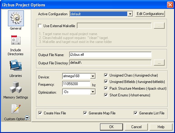
Make sure the Device selected is atmega168 and the Frequency use is 11059200 hz.
After compiling and simulating our code we are ready to down load the code using the AVRJazz Mega168 bootloader facility. The bootloader program is activated by pressing the user switch and reset switch at the same time; after releasing both switches, the 8 blue LED indicator will show that the bootloader program is activate and ready to received command from Atmel AVR Studio 4 STK500/AVRISP program.
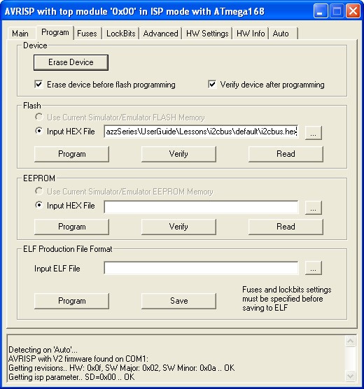
We choose the HEX file and press the Program Button to down load the code into the AVRJazz Mega168 board.

Now it’s time to relax and enjoy your hard work by watching your AVR microcontroller TWI peripheral in action:

Tuesday, 24 September 2013

Build Your Own Microcontroller Based PID Control Line Follower Robot (LFR) – Second Part

ne of the interesting parts in building the Line Follower Robot is; you could start it with a very simple version by using just two transistors with the LED and LDR for sensor (Build Your Own Transistor Based Mobile Line Follower Robot – First Part) and enhance it to the programmable version that use microcontroller as the brain for controlling the robot. The reason of using the microcontroller for the Line Follower Robot is we need to make more robust, reliable and flexible robot which you could not have it from the discrete electronics component robot without changing most of the electronic circuit design.

The advantages in building the microcontroller based Line Follower Robot (LFR) is we could take the advantage of microcontroller’s ALU (Arithmetic Logic Unit) to compute mathematics equation to perform the industrial standard Proportional, Integral and Derivative control or known as PID control. On this tutorial we will learn to build the LFR using the powerful Atmel AVR ATMega168 microcontroller and at the same time we will learn to utilize many of the AVR ATMega168 microcontroller sophisticated features to support our Line Follower Robot.
Now let’s check out all the exciting features of this Line Follower Robot that we are going to build:
  • Fully implement the industrial standard Proportional, Integral and Derivative (PID) control with flexible PID tuning parameter using the AVR ATMega168 UART peripheral and store the parameter to the AVR ATMega168 microcontroller build-in 512 Bytes EEPROM
  • Use five infra red reflective object sensor for the black line sensor with Microchip MCP23008 8-bit I2C (read as I square C) I/O expander chip to talk to the AVR ATMega168 Microcontroller I2C peripheral
  • 4.5 Volt to 5 Volt DC to DC Step-Up using Maxim MAX756 for powering both the electronics circuits and the DC motors. This will ensure the electronics circuits and the DC motors keep working properly even though the battery voltage level drops below 4.5 Volt.
  • Use the AVR ATMega168 ADC (Analog to Digital Converter) peripheral to control the maximum speed of the robot.
  • Use the AVR ATMega168 PWM (Pulse Width Modulation) peripheral to drive the SGS-Thomson L293D chip to control the DC motors speed
BRAM II Chassis Construction
The first version of BRAM (Beginner’s Robot Autonomous Mobile), used CD/DVD for the chassis; in this version of BRAM, I use the acrylic as the base for the chassis; which is easy to shape, drill and it came with transparent look and many color to choose too. You could read more information about the first BRAM version on my previous posted blog Building BRAM your first Autonomous Mobile Robot Using Microchip PIC Microcontroller.

BRAM II construction material parts:
  • Acrylic for the BRAM chassis
  • Two geared DC motors with wheels rated 4.5 to 5 volt (25-30mA) with the wheel or you could use the modified servo motor (it’s a servo motor without the electronics’s control board)
  • One 3 x 1.5 volt AA battery holder with on-off switch
  • One plastic bead (usually it use for the neck less) and one paper clip for the caster
  • Enough nuts, bolts and PCB (printed circuit board) standoff.
BRAM construction consists of two decks, where the lower deck is used to hold the battery, DC motors and the sensor circuit while the upper deck is used to hold the motor controller circuit and the AVRJazz Mega168 board.


Put the 3xAA battery and sensor circuit on the lower deck and the motor control circuit at the bottom of the upper deck.


Now connect the battery power terminal, sensor circuit power terminal, DC motor power terminal to the Motor Control Circuit and screw the upper deck on the lower deck.

Finally put the AVRJazz Mega168 board on top of the upper deck and connect all the connectors from the Motor Control Circuit and Sensor Circuit to the AVRJazz Mega168 board, now you are ready to program the robot.
BRAM II Electronic Circuit and Program
BRAM II use quite sophisticated power mechanism circuit as well as the line sensor circuit design to make it more robust line follower robot.

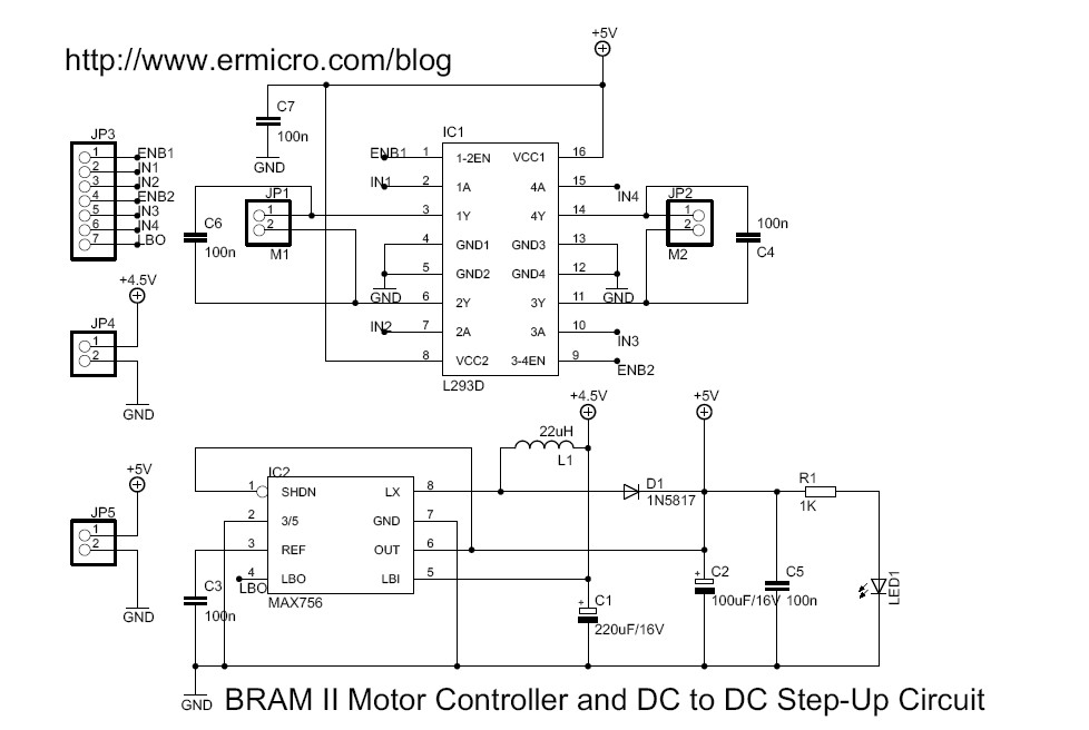
The 3xAA battery is the main power source for both the electronics circuits and the DC motors, because the Line Follower Robot need to accurately control the motor speed and tracking the line; therefore BRAM II design use DC to DC step-up circuit to boost 4.5 volt level up to the 5 volt level using the Maxim MAX756, you could read more about MAX756 in my previous posted blog Powering your Microcontroller’s Based Project. The advantages of using the power boost is all the electronics circuits and DC motors will guarantee to get proper voltage level even though the main power source theoretically drops down to 2 volt level; although I’ve never try this.
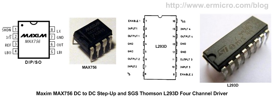
For the DC motors controller we simply use the two channels SGS-Thomson L293D H-Bridge motor driver chips, this chip is used to make circuit simpler and robust compared to the standard transistor’s base H-Bridge driver. The L293D chip is able to handle non repetitive current up to 1.2 A for each channels and its already equipped with the internal EMF (Electromotive Force) protection diodes.
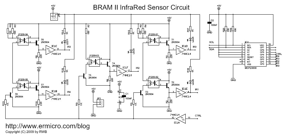
For the line sensor circuit I decided to take advantage of the Microchip MCP23008 I2C 8-bit I/O expander to minimized the AVR Mega168 microcontroller I/O ports usage and at the same time it serve as a learning tools of how to expand your microcontroller I/O port using the Microchip MCP23008. Here is the complete PDF schematic for the AVRJazz Mega168 board, Motor Controller & DC to DC Step-Up and the Sensor Circuit.
The last is the ATMega168 UART peripheral, which is used to setup our BRAM II PID control parameter; by using the AVRJazz Mega168 board build in RS323 voltage level converter; we could connect the RS232 communication (COM) port directly to the computer COM port or you could use the USB to RS232 converter as I did and use the MS Windows HyperTerminal or puTTY program to enter the PID control setup. You could read more about AVR UART peripheral on my previous posted blog Working with AVR microcontroller Communication Port Project.
The following are the list of hardware and software used in this tutorial:
  • Supporting chips: SGS Thomson L293D, Maxim MAX756, Microchip MCP23008 and 74HC14 Schmitt trigger
  • Five Junye JY209-01 reflective object sensor.
  • For the detail electronics components such as transistors, capacitors and resistors please refer to the schematic above.
  • AVRJazz Mega168 board from ermicro which base on the AVR ATmega168 microcontroller.
  • WinAVR for the GNU’s C compiler v4.3.0 (WinAVR 2009313).
  • Atmel AVR Studio v4.17 for the coding and debugging environment.
  • STK500 programmer from AVR Studio 4, using the AVRJazz Mega168 board STK500 v2.0 bootloader facility.
Ok that’s a brief explanation of the BRAM II Line Follower Robot project electronic circuits that we are going to build; now let’s take a look at the C code that makes the BRAM II brain:
//***************************************************************************
//  File Name  : bramlfr.c
//  Version  : 1.0
//  Description  : BRAM Line Follower Robot (LFR)
//               : LFR with PID Controller
//  Author       : RWB
//  Target       : AVRJazz Mega168 Board
//  Compiler     : AVR-GCC 4.3.0; avr-libc 1.6.2 (WinAVR 20090313)
//  IDE          : Atmel AVR Studio 4.17
//  Programmer   : AVRJazz Mega168 STK500 v2.0 Bootloader
//               : AVR Visual Studio 4.17, STK500 programmer
//  Last Updated : 28 July 2009
//***************************************************************************
#include <avr/io.h>
#include <util/delay.h>
#include <avr/interrupt.h>
#include <compat/twi.h>
#include <stdio.h>
#include <avr/pgmspace.h>
#include <avr/eeprom.h>
// BRAM Debugging Mode, 0-Debug Off, 1-Debug On
#define BRAM_DEBUG 0
#define BAUD_RATE 19200
#define MAX_TRIES 50
#define MCP23008_ID    0x40  // MCP23008 Device Identifier
#define MCP23008_ADDR  0x0E  // MCP23008 Device Address
#define IODIR 0x00           // MCP23008 I/O Direction Register
#define GPPU  0x06           // MCP23008 I/O Pull-Up Resistor Register
#define GPIO  0x09           // MCP23008 General Purpose I/O Register
#define I2C_START 0
#define I2C_DATA 1
#define I2C_DATA_ACK 2
#define I2C_STOP 3
#define ACK 1
#define NACK 0
// Define BRAM Steering
#define MOVE_FORWARD  0
#define TURN_LEFT     1
#define TURN_RIGHT    2
#define ROTATE_LEFT   3
#define ROTATE_RIGHT  4
#define MOVE_BACKWARD 5
#define FULL_STOP     6
// Define BRAM Sensor
#define MAX_MAP 24
#define TARGET_VAL 60
#define MAX_SENSOR_MAP 120
// Define BRAM Variables
const unsigned int sensor_map[] PROGMEM = {
  0b00000,0,
  0b00001,10,
  0b00011,20,
  0b00010,30,
  0b00111,40,
  0b00110,50,
  0b00100,60,
  0b01100,70,
  0b11100,80,
  0b01000,90,
  0b11000,100,
  0b10000,110
};
unsigned char MaxSpeed;                         // Hold Motor Maximum Speed
unsigned int Kp,Ki,Kd;                          // PID Parameters
int prev_res=0, prev_err_1=0, prev_err_2=0;     // PID Control Variables
void uart_init(void)
{
  UBRR0H = (((F_CPU/BAUD_RATE)/16)-1)>>8; // set baud rate
  UBRR0L = (((F_CPU/BAUD_RATE)/16)-1);
  UCSR0B = (1<<RXEN0)|(1<<TXEN0);   // enable Rx & Tx
  UCSR0C=  (1<<UCSZ01)|(1<<UCSZ00);           // config USART; 8N1
}
void uart_flush(void)
{
  unsigned char dummy;
  while (UCSR0A & (1<<RXC0)) dummy = UDR0;
}
int uart_putch(char ch,FILE *stream)
{
   if (ch == '\n')
    uart_putch('\r', stream);
   while (!(UCSR0A & (1<<UDRE0)));
   UDR0=ch;
   return 0;
}
int uart_getch(FILE *stream)
{
   unsigned char ch;
   while (!(UCSR0A & (1<<RXC0)));
   ch=UDR0;  

   /* Echo the Output Back to terminal */
   uart_putch(ch,stream);       

   return ch;
}
void ansi_cl(void)
{
  // ANSI clear screen: cl=\E[H\E[J
  putchar(27);
  putchar('[');
  putchar('H');
  putchar(27);
  putchar('[');
  putchar('J');
}
void ansi_me(void)
{
  // ANSI turn off all attribute: me=\E[0m
  putchar(27);
  putchar('[');
  putchar('0');
  putchar('m');
}
void ansi_cm(unsigned char row,unsigned char col)
{
  // ANSI cursor movement: cl=\E%row;%colH
  putchar(27);
  putchar('[');
  printf("%d",row);
  putchar(';');
  printf("%d",col);
  putchar('H');
}
// BRAM Steering Function
// PD2 - Input 1 (Left Motor), PD3 - Input 2 (Left Motor)
// PD4 - Input 3 (Right Motor), PD7 - Input 4 (Right Motor)
void BRAM_Steer(unsigned char steer)
{
  switch(steer) {
    case MOVE_FORWARD:
   PORTD &= ~(1 << PD4); PORTD |= (1 << PD7);  // Right Motor On Forward
   PORTD &= ~(1 << PD2); PORTD |= (1 << PD3);  // Left Motor On Forward
      break;
    case TURN_LEFT:
     PORTD &= ~(1 << PD4); PORTD |= (1 << PD7);  // Right Motor On Forward
   PORTD &= ~(1 << PD2); PORTD &= ~(1 << PD3); // Left Motor Off
      break;
    case TURN_RIGHT:
   PORTD &= ~(1 << PD4); PORTD &= ~(1 << PD7); // Right Motor Off
   PORTD &= ~(1 << PD2); PORTD |= (1 << PD3);  // Left Motor On Forward
      break;
    case ROTATE_LEFT:
    PORTD &= ~(1 << PD4); PORTD |= (1 << PD7);  // Right Motor On Forward
   PORTD |= (1 << PD2); PORTD &= ~(1 << PD3);  // Left Motor On Reverse
          break;
    case ROTATE_RIGHT:
   PORTD |= (1 << PD4); PORTD &= ~(1 << PD7);  // Right Motor On Reverse
   PORTD &= ~(1 << PD2); PORTD |= (1 << PD3);  // Left Motor On Forward
          break;
    case MOVE_BACKWARD:
    PORTD |= (1 << PD4); PORTD &= ~(1 << PD7);  // Right Motor On Reverse
   PORTD |= (1 << PD2); PORTD &= ~(1 << PD3);  // Left Motor On Reverse
          break;
    case FULL_STOP:
   PORTD &= ~(1 << PD4); PORTD &= ~(1 << PD7);  // Right Motor Off
   PORTD &= ~(1 << PD2); PORTD &= ~(1 << PD3);  // Left Motor Off
          break;
  }
}
// BRAM Motor Speed Control
// PD5 - OC0B -> ENB1 (Left Motor)
// PD6 - OC0A -> ENB2 (Right Motor)
void BRAM_DriveMotor(int left_speed, int right_speed)
{
  unsigned char left_pwm,right_pwm;
  if (left_speed >= 0 && right_speed >= 0) {
    // Move Forward
    BRAM_Steer(MOVE_FORWARD);

    left_pwm=left_speed;
    right_pwm=right_speed;
  } else if (left_speed < 0 && right_speed < 0) {
    // Move Backward
    BRAM_Steer(MOVE_BACKWARD);
    left_pwm=left_speed * -1;
    right_pwm=right_speed * -1;
  } else if (left_speed < 0 && right_speed >= 0) {
    // Rotate Left
    BRAM_Steer(ROTATE_LEFT);
    left_pwm=left_speed * -1;
    right_pwm=right_speed;
  } else if (left_speed >= 0 && right_speed < 0) {
    // Rotate Right
    BRAM_Steer(ROTATE_RIGHT);
    left_pwm=left_speed;
    right_pwm=right_speed * -1;
  } else {
    // Full Stop
    BRAM_Steer(FULL_STOP);
    left_pwm=0;
    right_pwm=0;
  }
  // Assigned the value to the PWM Output Compare Registers A and B
  OCR0A=right_pwm;
  OCR0B=left_pwm;
}
/* START I2C Routine */
unsigned char i2c_transmit(unsigned char type) {
  switch(type) {
     case I2C_START:    // Send Start Condition
       TWCR = (1 << TWINT) | (1 << TWSTA) | (1 << TWEN);
       break;
     case I2C_DATA:     // Send Data with No-Acknowledge
       TWCR = (1 << TWINT) | (1 << TWEN);
       break;
     case I2C_DATA_ACK: // Send Data with Acknowledge
       TWCR = (1 << TWEA) | (1 << TWINT) | (1 << TWEN);
       break;
     case I2C_STOP:     // Send Stop Condition
       TWCR = (1 << TWINT) | (1 << TWEN) | (1 << TWSTO);
       return 0;
  }
  // Wait for TWINT flag set on Register TWCR
  while (!(TWCR & (1 << TWINT)));
  // Return TWI Status Register, mask the prescaller bits (TWPS1,TWPS0)
  return (TWSR & 0xF8);
}
char i2c_start(unsigned int dev_id, unsigned int dev_addr, unsigned char rw_type)
{
  unsigned char n = 0;
  unsigned char twi_status;
  char r_val = -1;
i2c_retry:
  if (n++ >= MAX_TRIES) return r_val;
  // Transmit Start Condition
  twi_status=i2c_transmit(I2C_START);

  // Check the TWI Status
  if (twi_status == TW_MT_ARB_LOST) goto i2c_retry;
  if ((twi_status != TW_START) && (twi_status != TW_REP_START)) goto i2c_quit;
  // Send slave address (SLA_W)
  TWDR = (dev_id & 0xF0) | ((dev_addr << 1) & 0x0E) | rw_type;
  // Transmit I2C Data
  twi_status=i2c_transmit(I2C_DATA);
  // Check the TWSR status
  if ((twi_status == TW_MT_SLA_NACK) || (twi_status == TW_MT_ARB_LOST)) goto i2c_retry;
  if (twi_status != TW_MT_SLA_ACK) goto i2c_quit;
  r_val=0;
i2c_quit:
  return r_val;
}
void i2c_stop(void)
{
  unsigned char twi_status;
  // Transmit I2C Data
  twi_status=i2c_transmit(I2C_STOP);
}
char i2c_write(char data)
{
  unsigned char twi_status;
  char r_val = -1;
  // Send the Data to I2C Bus
  TWDR = data;
  // Transmit I2C Data
  twi_status=i2c_transmit(I2C_DATA);
  // Check the TWSR status
  if (twi_status != TW_MT_DATA_ACK) goto i2c_quit;
  r_val=0;
i2c_quit:
  return r_val;
}
char i2c_read(char *data,char ack_type)
{
  unsigned char twi_status;
  char r_val = -1;               

  if (ack_type) {
    // Read I2C Data and Send Acknowledge
    twi_status=i2c_transmit(I2C_DATA_ACK);
    if (twi_status != TW_MR_DATA_ACK) goto i2c_quit;
  } else {
    // Read I2C Data and Send No Acknowledge
    twi_status=i2c_transmit(I2C_DATA);
    if (twi_status != TW_MR_DATA_NACK) goto i2c_quit;
  }
  // Get the Data
  *data=TWDR;
  r_val=0;
i2c_quit:
  return r_val;
}
void Write_MCP23008(unsigned char reg_addr,unsigned char data)
{
   // Start the I2C Write Transmission
   i2c_start(MCP23008_ID,MCP23008_ADDR,TW_WRITE);
   // Sending the Register Address
   i2c_write(reg_addr);
   // Write data to MCP23008 Register
   i2c_write(data);
   // Stop I2C Transmission
   i2c_stop();
}
unsigned char Read_MCP23008(unsigned char reg_addr)
{
   char data;
   // Start the I2C Write Transmission
   i2c_start(MCP23008_ID,MCP23008_ADDR,TW_WRITE);
   // Read data from MCP23008 Register Address
   i2c_write(reg_addr);
   // Stop I2C Transmission
   i2c_stop();

   // Re-Start the I2C Read Transmission
   i2c_start(MCP23008_ID,MCP23008_ADDR,TW_READ);
   i2c_read(&data,NACK);

   // Stop I2C Transmission
   i2c_stop();

   return data;
}
unsigned int BRAM_IRSensor()
{
   static unsigned int old_val = TARGET_VAL;
   unsigned int map_val;
   unsigned char sensor_val,ptr;
   // Turn On the Sensor IR LED
   Write_MCP23008(GPIO,0b00011111);    

   // Read sensor
   sensor_val = Read_MCP23008(GPIO) & 0x1F;
   // Turn Off the Sensor IR LED
   Write_MCP23008(GPIO,0b00111111);
   // Return Value from Sensor Map
   map_val=TARGET_VAL;        // Default always on center
   if (sensor_val > 0) {
     for(ptr = 0; ptr < MAX_MAP; ptr++) {
       // Now get the sensor map value
       if (pgm_read_word(sensor_map + ptr) == sensor_val) {
  map_val=pgm_read_word(sensor_map + ptr + 1);
       }
     }
     old_val=map_val;   // Save the Current IR Array Value
   } else {
     map_val=0;
     // Adjust for zero result if previous value greater than 5
     if (old_val > TARGET_VAL) map_val=MAX_SENSOR_MAP;
   }
   // Display IR Sensor Value in Debugging Mode
#if BRAM_DEBUG
   ansi_cm(3,1);
   printf("IR Sensor: %02x, Map Value: %03d",sensor_val,map_val);
#endif
   return map_val;
}
void BRAM_PIDControl(unsigned int sensor_val)
{
   int motor_res,err_func;
   float KP,KI,KD,cont_res;
   // Get the Error Function
   err_func=sensor_val - TARGET_VAL;
   // Divide all the PID parameters for decimal value
   KP=Kp * 0.1;
   KI=Ki * 0.01;
   KD=Kd * 0.01;
   // Calculate the Motor Response using PID Control Equation
   cont_res=(float)(prev_res + KP * (err_func - prev_err_1) + KI * (err_func + prev_err_1)/2.0
               + KD * (err_func - 2.0 * prev_err_1 + prev_err_2));        

   // Now we have to Limit the control response to the Maximum of our motor PWM Motor Value
   motor_res=(int)cont_res;
   if (motor_res > MaxSpeed)
     motor_res = MaxSpeed;
   if (motor_res < -MaxSpeed)
     motor_res = -MaxSpeed;  

   // Save the Motor Response and Error Function Result
   prev_res=motor_res;
   prev_err_2=prev_err_1;
   prev_err_1=err_func;

   // Display Motor Response Value in Debugging Mode
#if BRAM_DEBUG
   ansi_cm(4,1);
   printf("Motor Response Factor: %d   ",motor_res);
#endif
   // Negative result mean BRAM is on the right, so we need to adjust to the left
   // Positive result mean BRAM is on the left, so we need to adjust to the right
   if (motor_res < 0)
     BRAM_DriveMotor(MaxSpeed + motor_res,MaxSpeed); // Left less speed, Right full speed
   else
     BRAM_DriveMotor(MaxSpeed,MaxSpeed - motor_res); // Left full speed, Right less speed
}
unsigned int getnumber(unsigned int min, unsigned int max)
{
  int inumber;
  scanf("%d",&inumber);
  if (inumber < min || inumber > max) {
    printf("\n\nInvalid [%d to %d]!",min,max);
    _delay_ms(500);
    return -1;
  }
  return inumber;
}
void Read_Parameter(void)
{
  // Read the Kp,Ki and Kd From EEPROM at Address: 0x00,0x02,0x04
  Kp=eeprom_read_word((unsigned int*) 0x0000);
  Ki=eeprom_read_word((unsigned int*) 0x0002);
  Kd=eeprom_read_word((unsigned int*) 0x0004);
}
// Assign I/O stream to UART
FILE uart_str = FDEV_SETUP_STREAM(uart_putch, uart_getch, _FDEV_SETUP_RW);
int main(void)
{
  unsigned char mode,press_tm;
  unsigned int ir_sensor;
  int ichoice;
  // Initial PORT Used
  DDRB = 0b11111110;     // Set PORTB: PB0=Input, Others as Output
  PORTB = 0;
  DDRC = 0b00000000;     // Set PORTC: Input
  PORTC = 0xFF;          // Pull-Up Input
  DDRD = 0b11111111;     // Set PORTD: Output
  PORTD = 0;
  // Define Output/Input Stream
  stdout = stdin = &uart_str;
  // Initial UART Peripheral
  uart_init();
  // Initial BRAM Terminal Screen
  ansi_me();
  ansi_cl();                            // Clear Screen
#if BRAM_DEBUG
  ansi_cm(1,1);
  printf("Welcome to AVRJazz Mega168 BRAM Debugging Mode");
#endif
  // Initial The 8-bit PWM 0
  // Fast PWM Frequency = fclk / (N * 256), Where N is the prescale
  // f_PWM = 11059200 / (8 * 256) = 5400 Hz
  TCCR0A = 0b10100011; // Fast PWM 8 Bit, Clear OCA0/OCB0 on Compare Match, Set on TOP
  TCCR0B = 0b00000010; // Used 8 Prescaler
  TCNT0 = 0;           // Reset TCNT0
  OCR0A = 0;           // Initial the Output Compare register A & B
  OCR0B = 0;
  // Initial ATMega168 TWI/I2C Peripheral
  TWSR = 0x00;         // Select Prescale of 1
  // SCL frequency = 11059200 / (16 + 2 * 48 * 1) = 98.743 kHz
  TWBR = 0x30;        // 48 Decimal
  // Initial the MCP23008 Devices GP0 to GP4 Input, GP5 to GP7 Output
  Write_MCP23008(IODIR,0b00011111);
  Write_MCP23008(GPPU,0b00011111);    // Enable Pull-Up on Input
  Write_MCP23008(GPIO,0b00111111);    // Reset all the Output Port, Make GP5 High
  // Set ADCSRA Register on ATMega168
  ADCSRA = (1<<ADEN) | (1<<ADPS2) | (1<<ADPS1);
  // Set ADMUX Register on ATMega168
  ADMUX = (1<<ADLAR); // Use Right Justified, Select Channel 0
  // Initial the Motor
  BRAM_DriveMotor(0,0);
  mode=0;              // Default BRAM Off
  press_tm=0;
  // Initial PID Control Variables
  prev_res=0;
  prev_err_1=0;
  prev_err_2=0;
  MaxSpeed = 150;   // Initial Maximum Speed
   // Read Default BRAM Parameter from EEPROM
  Read_Parameter();

  for(;;) {            // Loop Forever
    // Check if Button is pressed than enter to the Setup Mode
    if (bit_is_clear(PINB, PB0)) {          // if button is pressed
      _delay_us(100);                       // Wait for debouching
      if (bit_is_clear(PINB, PB0)) {
        press_tm++;
        if (press_tm > 100) {
          press_tm=0;
          mode++;
          if (mode > 2)
         mode = 0;
         }
       }
     }      

     // Start conversion by setting ADSC on ADCSRA Register
     ADCSRA |= (1<<ADSC);
     // wait until convertion  complete ADSC=0 -> Complete
     while (ADCSRA & (1<<ADSC));
     // Get ADC the Result
     MaxSpeed = ADCH;
     if (mode == 0) {
       // Initial PID Control Variables
       prev_res=0;
       prev_err_1=0;
       prev_err_2=0;
     }
    if (mode == 1) {
      // Read the IR Sensor
      ir_sensor=BRAM_IRSensor();
      // Give some delay Before PID Calculation
      _delay_us(50);
      // Execute the BRAM LFR PID Controller
      BRAM_PIDControl(ir_sensor);
    }
    // Entering BRAM PID Setup Mode
    if (mode == 2) {
      // Stop BRAM Motors
      BRAM_DriveMotor(0,0);
      // Initial BRAM Terminal Screen
      uart_flush();                         // Flush UART
      ansi_me();
      ansi_cl();                            // Clear Screen
      ansi_cm(1,1);
      printf("Welcome to AVRJazz Mega168 BRAM Setup");
      ansi_cm(3,1);
      printf("BRAM Maximum Speed Value: %d",MaxSpeed);

      ansi_cm(5,1);
      printf("1. Kp - Proportional Parameter Factor (%d)\n",Kp);
      printf("2. Ki - Integral Parameter Factor (%d)\n",Ki);
      printf("3. Kd - Derivative Parameter Factor (%d)\n",Kd);
      printf("4. Save Parameters to the EEPROM\n");
      printf("5. Refresh Setup\n");
      printf("6. Exit\n");
      printf("\nEnter Choice: ");
      if ((ichoice=getnumber(1,6)) < 0) continue; 

      switch (ichoice) {
     case 1:  // Kp Parameter
    printf("\n\nKp Parameter [0-1000]: ");
    if ((Kp=getnumber(0,1000)) < 0) continue;
    break;
            case 2:  // Ki Parameter
    printf("\n\nKi Parameter [0-1000]: ");
    if ((Ki=getnumber(0,1000)) < 0) continue;
    break;
            case 3:  // Kd Parameter
    printf("\n\nKd Parameter [0-1000]: ");
    if ((Kd=getnumber(0,1000)) < 0) continue;
    break;
            case 4:  // Save to EEPROM
    // Write the Kp,Ki and Kd to EEPROM Address: 0x0000,0x0002,0x0004
    eeprom_write_word((unsigned int*) 0x0000,Kp);
    eeprom_write_word((unsigned int*) 0x0002,Ki);
    eeprom_write_word((unsigned int*) 0x0004,Kd);
    // Read BRAM Parameter from EEPROM
                  Read_Parameter();
    break;
     case 5:  // Refresh Setup
        // Start conversion by setting ADSC on ADCSRA Register
           ADCSRA |= (1<<ADSC);
           // wait until convertion  complete ADSC=0 -> Complete
                  while (ADCSRA & (1<<ADSC));
           // Get ADC the Result
           MaxSpeed = ADCH;
    // Read BRAM Parameter from EEPROM
                  Read_Parameter();
    break;
     case 6:  // Exit Setup
    mode = 0;
    ansi_cl();
    break;
      }
    }
  }

  return 0;            // Standard Return Code
}
/* EOF: bramflr.c */
The Power and DC Motor Control Circuits
The power circuit uses the Maxim MAX756 CMOS step-up DC to DC switching regulator to boost the 4.5 volt battery power up to 5 volt level.

The Maxim MAX756 could still work well by using just two AA Alkaline batteries (3 Volt) or two AA NiMH rechargeable batteries (2.4 Volt) and still giving you a solid 5 volt output to power your Line Follower Robot. Therefore by using this step-up switching regulator we could ensure BRAM II electronic circuits and DC motors will still work in their maximum performance until all the battery power being drained out.

BRAM II uses the “differential drive” for steering method which use two DC motors mounted in fixed positions on the left and right side of the BRAM II chassis. Each of these DC motors could rotate independently both in forward or reverse direction; therefore by adjusting both the motor’s rotation direction and speed we could easily control the BRAM II movement.

The BRAM DC motors are connected to the popular dual channel H-Bridge SGS-Thompson L293D chip; by feeding the right logic from the AVR ATMega168 PORT-D I/O (PD2,PD3,PD4 and PD7) to the 4 buffers inputs we could get the desired result:

The C function that control the BRAM II steering is BRAM_Steer(), which simply supply the right logic to the L293D chip input ports according to the truth table shown above:
// Define BRAM Steering
#define MOVE_FORWARD  0
#define TURN_LEFT     1
#define TURN_RIGHT    2
#define ROTATE_LEFT   3
#define ROTATE_RIGHT  4
#define MOVE_BACKWARD 5
#define FULL_STOP     6
...
...
void BRAM_Steer(unsigned char steer)
{
  switch(steer) {
    case MOVE_FORWARD:
   PORTD &= ~(1 << PD4); PORTD |= (1 << PD7);  // Right Motor On Forward
   PORTD &= ~(1 << PD2); PORTD |= (1 << PD3);  // Left Motor On Forward
      break;
    case TURN_LEFT:
     PORTD &= ~(1 << PD4); PORTD |= (1 << PD7);  // Right Motor On Forward
   PORTD &= ~(1 << PD2); PORTD &= ~(1 << PD3); // Left Motor Off
      break;
    case TURN_RIGHT:
   PORTD &= ~(1 << PD4); PORTD &= ~(1 << PD7); // Right Motor Off
   PORTD &= ~(1 << PD2); PORTD |= (1 << PD3);  // Left Motor On Forward
      break;
    case ROTATE_LEFT:
    PORTD &= ~(1 << PD4); PORTD |= (1 << PD7);  // Right Motor On Forward
   PORTD |= (1 << PD2); PORTD &= ~(1 << PD3);  // Left Motor On Reverse
      break;
    case ROTATE_RIGHT:
   PORTD |= (1 << PD4); PORTD &= ~(1 << PD7);  // Right Motor On Reverse
   PORTD &= ~(1 << PD2); PORTD |= (1 << PD3);  // Left Motor On Forward
      break;
    case MOVE_BACKWARD:
    PORTD |= (1 << PD4); PORTD &= ~(1 << PD7);  // Right Motor On Reverse
   PORTD |= (1 << PD2); PORTD &= ~(1 << PD3);  // Left Motor On Reverse
      break;
    case FULL_STOP:
   PORTD &= ~(1 << PD4); PORTD &= ~(1 << PD7);  // Right Motor Off
   PORTD &= ~(1 << PD2); PORTD &= ~(1 << PD3);  // Left Motor Off
      break;
  }
}
The DC motor speed is controlled by supplying the PWM (Pulse Width Modulation) to L293D input enable ENABLE-1 and ENABLE-2 pins. In this design we use the AVR ATMega168 8-bit Timer/Counter0 PWM peripheral which give two independent PWM out on PD5 (OC0B) and PD6 (OC0A). For more information about using the PWM peripheral you could read my previous posted blogs Introduction to AVR Microcontroller Pulse Width Modulation (PWM) and Controlling Motor with AVR ATTiny13 PWM and ADC Project.
One of the important aspect when building a robot is to choose the precise PWM frequency for your DC motor as this could effecting your DC motor response to the PWM signal supplied to it. On this tutorial I apply 5400 Hz for the PWM frequency as it gives optimal response to the DC motor used on BRAM II. Following is the C code showing the AVR ATMega168 8-bit Timer/Counter0 PWM peripheral initialization:
// Initial The 8-bit Timer/Counter0 PWM
// Fast PWM Frequency = fclk / (N * 256), Where N is the prescaler
// f_PWM = 11059200 / (8 * 256) = 5400 Hz
TCCR0A = 0b10100011; // Fast PWM 8 Bit, Clear OCA0/OCB0 on Compare Match, Set on TOP
TCCR0B = 0b00000010; // Used 8 for the prescale
TCNT0 = 0;           // Reset TCNT0
OCR0A = 0;           // Initial the Output Compare register A & B
OCR0B = 0;
By varying the value assigned to the AVR ATMega168 microcontroller output compare register OCR0A and OCR0B we could varying the PWM signal from 0% to 100% (0 to 255). The C code that serve that purpose is the BRAM_DriveMotor() function which accept two arguments both for left and right DC motor speed. This function will also accept negative value arguments which are translated to the reverse DC motor rotation.
void BRAM_DriveMotor(int left_speed, int right_speed)
{
  unsigned char left_pwm,right_pwm;

  ...
  ...
  // Assigned the value to the PWM Output Compare Registers A and B
  OCR0A=right_pwm;
  OCR0B=left_pwm;
}
One last thing before you wire your DC motor power terminal to the L293D chip, is to find your DC motor power polarity where it give you the correct rotation direction base on the truth table shown above.
The Line Sensor Circuit
The line sensor is designed to takes advantage of the infra red reflective object sensor Junye JY209-01 or you could replace it with Fairchild QRE00034 to sense the black tape line; when the sensor is above the black tape line the infra red beam will not reflected back to the photo transistor and the photo transistor will turn off, if the sensor is on the white surface than the infra red beam will reflected back to the photo transistor and the photo transistor will turn on.

To make the sensor more sensitive and provide a smooth digital transition between “0” to “1” or vice verse; I use the NPN 2N3904 BJT to form the Darlington pair with the photo transistor to amplify the infra red signal received by the photo transistor, then feed the output (taken from the emitter) to the 74HC14 hex inverting Schmitt trigger chip. The infra red LED is controlled by NPN 2N3904 BJT through one of the 74HC14 inverting Schmitt trigger gate. For more information of using the transistor as switch you could read my previous blog Using Transistor as Switch.

In order to lower the current taken from the MAX756 DC to DC Step-Up, two of the infra LED pairs are connected serially; this connection will produce about 3 x 20mA (60mA) instead of 5 x 20mA (100mA). I use the blue LED for displaying the sensor status as this type of LED need lesser current to produce decent light intensity compared to other LED. The reason why we have to carefully calculate the current needed, because all the electronic circuits and DC motors power is taken from the MAX756 chip which only capable to operate up to 200mA on 5 Volt output.

Finally the entire sensor output (IR0 to IR4) and input (CTRL) is connected to the Microchip MCP23008 I2C 8-bit I/O expander ports. The SCL and SDA pins connected directly to the AVR ATMega168 PORT-C PC5 (SCL) and PC4 (SDA) I2C bus pins.

As standard to all I2C devices; the MCP23008 has an unique 7 bits address consists of 4 bits device identification and 3 bits device physical address; the first 4 bits for MCP23008 device identification is “0100” and the last 3 bits of physical address is set to “111“, by connecting the A0, A1 and A2 pins to the 5 Volt.

The read and write C code to the MCP23008 chip is provided by the Read_MCP23008() and Write_MCP23008() functions respectively; these two functions used the MCP23008 I2C device protocol shown above to do this task. For more information of how to use the I2C devices please refer to my previous posted blog How to use I2C-bus on Atmel AVR Microcontroller.
Before we could use the MCP23008 I2C I/O expander, first we have to initialized the AVR ATMega168 microcontroller TWI (Two Wire Interfaces, Atmel own named for Philips I2C trademark) peripheral and assign the general purpose I/O GP0 to GP4 as the input port and GP5 to GP7 as the output port by writing to the MCP23008 IODIR register located on the address 0×00.
...
// Initial ATMega168 TWI/I2C Peripheral
TWSR = 0x00;         // Select Prescaler of 1
// SCL frequency = 11059200 / (16 + 2 * 48 * 1) = 98.743 khz
TWBR = 0x30;         // 48 Decimal
// Initial the MCP23008 Devices GP0 to GP4 Input, GP5 to GP7 Output
Write_MCP23008(IODIR,0b00011111);
Write_MCP23008(GPIO,0b00111111);    // Reset all the Output Port, Make GP5 High
Write_MCP23008(GPPU,0b00011111);    // Enable Pull-Up on Input
...
Now you could read the reflective sensor status through the GP0 to GP4 port in the MCP23008 GPIO register. To reduce the current consumed by these infra red LED; we only turn on these infra red LED when we read the data by setting the GP5 to “0” when we read the sensor and toggling back to “1” after we get the sensor status. The sensor reading task is done inside the BRAM_IRSensor() function.
...
// Turn On the Sensor IR LED
Write_MCP23008(GPIO,0b00011111);    

// Read sensor
sensor_val = Read_MCP23008(GPIO) & 0x1F;
// Turn Off the Sensor IR LED
Write_MCP23008(GPIO,0b00111111);
...
This function will also return the sensor value mapped according to the sensor_map array variable that is specifically designed to support our PID control algorithm.
// Define BRAM Variables
const unsigned int sensor_map[] PROGMEM = {
  0b00000,0,
  0b00001,10,
  0b00011,20,
  0b00010,30,
  0b00111,40,
  0b00110,50,
  0b00100,60,
  0b01100,70,
  0b11100,80,
  0b01000,90,
  0b11000,100,
  0b10000,110
};
If the black tape line is right at the center of all these five reflective sensors array, then the sensor circuit will return 0b00100, where the logical “1” means the third JY209-01 (connected to GP2) sensor position is right on the black tape line, while all the other sensors is on the white surface or logical “0“. This sensor’s value then will be mapped to the integer value 60 according to the sensor_map variable array above. This value later on will be used as our reference value (TARGET_VAL) for the PID control algorithm.

Now what happen if all of these sensors are out of the line, which mean the value returned by the sensor circuit will be 0b00000; the BRAM_IRSensor() function then will use it’s stored value (old_val variable) to determine whether the robot position is way out to the right of the line, it will return 0 or if the robot position is way out to the left of the line, it will return MAX_SENSOR_MAP (120). The following is the C code that serves that purpose:
// Define BRAM Sensor
#define MAX_MAP 24
#define TARGET_VAL 60
#define MAX_SENSOR_MAP 120
...
...
map_val=0;
// Adjust for zero result if previous value greater than TARGET_VAL
if (old_val > TARGET_VAL) map_val=MAX_SENSOR_MAP;
...
BRAM II Proportional, Integral and Derivative Control Algorithm
Now we come to the most interesting topics and yet it full of gray cloud and myth around it, especially for the robot builder. The proportional, integral and derivative control or PID for short actually is just one of the control methods that can be applied to the embedded system. The other popular controlling method includes the bang-bang and fuzzy logic is also widely used in the embedded system world.

From the diagram above you could see how I implement the PID control on the BRAM II Line Follower Robot. The BRAM_PIDControl() function get the reflective object sensor array output from the BRAM_IRSensor() function and calculate the required control response to steer correctly the BRAM II DC motors by supplying the required PWM value to the BRAM_DriveMotor() function.
The “Proportional Control” is used to fix the error produced by the line follower robot position toward the black tape line compared to reference value (TARGET_VAL) which represents the robot position is at the center of the line. Therefore we could write down the error function as this following formula:
ERROR = SENSOR_VALUE - TARGET_VALUE
The proportional control actually works similar to the gain (volume) control found at your stereo set where you could increase or decrease the music volume came out from the speaker, your ears act as the sensors which give you a feedback to your brain, while your target value is your preference music volume level. If  the music volume level suddenly become higher compared to your preference level (error occur) than you decrease the volume level and vice verse. This gain factor usually called as the Kp (proportional) factor in PID control term. Therefore we could right down the control response as this following formula:
RESPONSE = Kp x ERROR
As mention before the BRAM_IRSensor() function will return the sensor map value from 0 to 120 where 0 mean our robot position is way out to the right while 120 mean our robot position is way out to the left; when BRAM_IRSensor() function return 60, mean our robot is right at the center of the line.
ERROR = SENSOR_VALUE - TARGET_VAL = 60 - 60 = 0
RESPONSE = Kp x ERROR = 0
If the response is 0 mean we could drive our robot to the maximum speed, so we could call the BRAM_DriveMotor() function as follow:
BRAM_DriveMotor(Left_Max_PWM, Right_Max_PWM);
When BRAM_IRSensor() function return 0
ERROR = SENSOR_VALUE - TARGET_VAL = 0 - 60 = -60
RESPONSE = Kp x ERROR = - 60 Kp
The negative response mean we have to turn or arc to the left to make the correction, this could be done by reducing the left motor PWM value (reducing left motor speed), while keep the right motor PWM value on it maximum value.
BRAM_DriveMotor(Left_Max_PWM + RESPONSE, Right_Max_PWM);
When BRAM_IRSensor() function return 120
ERROR = SENSOR_VALUE - TARGET_VAL = 120 - 60 = 60
RESPONSE = Kp x ERROR = 60 Kp
The positive response mean we have to turn or arc to the right to make the correction, this could be done by reducing the right motor PWM value (reducing right motor speed), while keep the left motor PWM value on it maximum value.
BRAM_DriveMotor(Left_Max_PWM, Right_Max_PWM - RESPONSE);
The Kp constant value could be any number that will boost the response value, following is the C code part of the BRAM_PIDControl() function that implements the explanation above:
...
...
// Negative result mean BRAM is on the right, so we need to adjust to the left
// Positive result mean BRAM is on the left, so we need to adjust to the right
if (motor_res < 0)
  BRAM_DriveMotor(MaxSpeed + motor_res,MaxSpeed); // Left less speed, Right full speed
else
  BRAM_DriveMotor(MaxSpeed,MaxSpeed - motor_res); // Left full speed, Right less speed
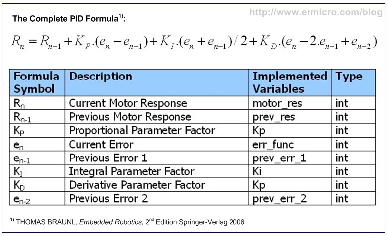
Using just the “Proportional Control” alone will resulting the zigzag steering behavior of the robot, therefore we have to combine it with “Integral Control” or “Derivative Control” or both of them to produce more accurate and stable robot’s steering movement. The following is the industrial standard PID control mathematic formula:

The “Integral Control” is used to reduce the accumulated error produced by the proportional control over the time or it’s also called a steady-state error, therefore the longer the robot produces an error (not in the center of the black line) the higher the integral control response output value.
The “Derivative Control” is used to speed up the proportional control error response, therefore the faster the robot produce an error such as zigzag steering movement the higher the derivative control response output value. In other word the derivative control will help to reduce the zigzag steering behavior of the robot.
Now as you understand the PID concept it’s time to convert or transform the PID formula above to the form that could be applied directly to the AVR ATMega168 microcontroller. For the purpose of this tutorial I will not describe of how we discretization this mathematic formula using the trapezoidal rule, the following is the complete PID control formula taken from the Thomas Braunl, Embedded Robotics, Second Edition Springer-Verlag 2006:

The following is the BRAM II Line Follower Robot C code that implements the PID control formula shown above:
...
unsigned char MaxSpeed;                         // Hold Motor Maximum Speed
unsigned int Kp,Ki,Kd;                          // PID Parameters
int prev_res=0, prev_err_1=0, prev_err_2=0;     // PID Control Variables
...
...
int motor_res,err_func;
float KP,KI,KD,cont_res;
// Get the Error Function
err_func=sensor_val - TARGET_VAL;
// Divide all the PID parameters for decimal value
KP=Kp * 0.1;
KI=Ki * 0.01;
KD=Kd * 0.01;
// Calculate the Motor Response using PID Control Equation
cont_res=(float)(prev_res + KP * (err_func - prev_err_1) + KI * (err_func + prev_err_1)/2.0
               + KD * (err_func - 2.0 * prev_err_1 + prev_err_2));        

// Now we have to Limit the control response to the Maximum of our motor PWM Motor Value
motor_res=(int)cont_res;
if (motor_res > MaxSpeed)
  motor_res = MaxSpeed;
if (motor_res < -MaxSpeed)
  motor_res = -MaxSpeed;
// Save the Motor Response and Error Function Result
prev_res=motor_res;
prev_err_2=prev_err_1;
prev_err_1=err_func;
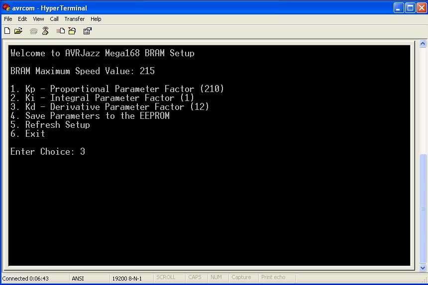
Once you run the program you could tune the PID control parameter by entering BRAM II setup mode (pressing the AVRJazz Mega168 board user switch twice) and connecting the AVRJazz Mega168 RS232 port to your computer terminal program such as Windows HyperTerminal or puTTY using these following guide lines:
  • Turn off all the Integral and Derivative control by zeroing the Ki and Kd parameters
  • Slowly increase the Proportional parameter (Kd) by the factor of ten (i.e. 10, 20, 30,…) and watch the robot behavior, if the robot tend to oscillate (zigzag) decrease this parameter
  • Slowly increase the Integral parameter (Ki) by the factor of one (i.e. 1, 2, 3,…) again watch the robot behavior until it nearly oscillate
  • Slowly increase the Derivative parameter (Kd) by the factor of one (i.e. 1, 2, 3,…) again watch the robot behavior until it become stable
  • You have to repeat these whole processes for different speed setting. Remember there are no such exact values for the PID parameter; the PID parameter depends heavily on your motor and sensor characteristic.

Inside the C Code
The program start by initializing the ATmega168 ports, than we continue with the UART peripheral, 8-bit Timer/Counter0 PWM peripheral, TWI peripheral and finally the ADC peripheral that is used to set the maximum speed of the DC Motors. Again most of the functions used in this project are based on my previous posted blogs mention above.
The UART Functions:
  • The UART functions are used to handle the communication with the PC:
  • uart_init() function is used to initialize the ATMega168 UART peripheral
  • uart_flush() function is used to empty the ATMega168 UART data register
  • uart_putch() function is used to put single character to the UART port
  • uart_getch() function is used to read single character from the UART port
  • ansi_cl() function is used to clear the ANSI emulation terminal screen
  • ansi_me() function is used to turn off all attribute on the ANSI terminal emulation
  • ansi_cm() function is used to move cursor on the ANSI terminal emulation
  • get_num() function is used to validate the user input; this function used the standard I/O C function scanf() to read the user input from the HyperTerminal or puTTY program
The application standard input and output stream is being redirected to both UART input and output with theses statements bellow:
// Assign I/O stream to UART
FILE uart_str = FDEV_SETUP_STREAM(uart_putch, uart_getch, _FDEV_SETUP_RW);
...
// Define Output/Input Stream
stdout = stdin = &uart_str;
The BRAM II Motor Functions:
The BRAM II motor functions are used to control the BRAM II motor steering and speed:
  • BRAM_Steer() function is used as the basic function to control the DC motor steer where it supply correct logic to the L293D chip
  • BRAM_DriveMotor() function is used to control the BRAM II steer and speed
  • BRAM_PIDControl() function is the BRAM II implementation of Porportional, Integral and Derivative control
The MCP23008 I2C Functions:
The I2C functions are used to perform reading and writing to the I2C devices:
  • i2c_transmit() function is used to transmit data to the I2C devices and wait for transmission done by monitoring the interrupt flag bit (TWINT) to be set.
  • i2c_start() function is used to send the I2C start condition
  • i2c_stop() function is used to send the I2C stop condition
  • i2c_write() function is used to write data to the I2C slave device register
  • i2c_read() function is used to read data from the I2C slave device register
  • Write_MCP23008() function is used to send data to the MCP23008 register
  • Read_MCP23008() function is used to read data from the MCP23008 register
Inside the infinite loop
BRAM II used the AVRJazz Mega168 board user potentiometer connected to the AVR ATMega168 microcontroller PC0 (ADC0) pin to determine the BRAM II maximum speed. The ADC value read from this port will be used as the maximum PWM value for controlling the motor’s speed. Because we use 8-bit PWM value, therefore we only need 8-bit ADC precision from the 10-bit ADC precision provided by the AVR ATMega168 ADC peripheral. This following C code showing the ADC peripheral initiation where we use the right justified for the ADC result taken from the ADCH register. For more information of working with ADC peripheral you could read my previous posted blog Analog to Digital Converter AVR C Programming.
...
// Set ADCSRA Register on ATMega168
ADCSRA = (1<<ADEN) | (1<<ADPS2) | (1<<ADPS1);
// Set ADMUX Register on ATMega168
ADMUX = (1<<ADLAR); // Use Right Justified, Select Channel 0
...
...
// Start conversion by setting ADSC on ADCSRA Register
ADCSRA |= (1<<ADSC);
// wait until convertion  complete ADSC=0 -> Complete
while (ADCSRA & (1<<ADSC));
// Get ADC the Result
MaxSpeed = ADCH;
Inside the for-loop (infinite loop) we simply read the AVRJazz Mega168 on board user switch (connected to AVR ATMega168 PB0 pin) and if pressed then we will run the BRAM II (mode 1) and if pressed twice (mode 2) we will enter the BRAM II parameter setup using Windows HyperTerminal or puTTY program and later on store this setup on the AVR ATMega168 microcontroller EEPROM.
...
// Write the Kp,Ki and Kd to EEPROM Address: 0x0000,0x0002,0x0004
eeprom_write_word((unsigned int*) 0x0000,Kp);
eeprom_write_word((unsigned int*) 0x0002,Ki);
eeprom_write_word((unsigned int*) 0x0004,Kd);
The stored PID control parameter later on will be read back from the EEPROM by the Read_Parameter() function every time we power on the BRAM II.
void Read_Parameter(void)
{
  // Read the Kp,Ki and Kd From EEPROM at Address: 0x00,0x02,0x04
  Kp=eeprom_read_word((unsigned int*) 0x0000);
  Ki=eeprom_read_word((unsigned int*) 0x0002);
  Kd=eeprom_read_word((unsigned int*) 0x0004);
}
Compile and Download the Code to the board
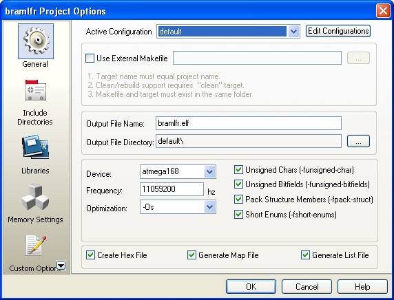
Before compiling the code, we have to make sure the AVR Studio 4.17 configuration is set properly by selecting menu project -> Configuration Option, the Configuration windows will appear as follow:

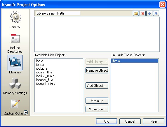
Make sure the Device selected is atmega168 and the Frequency use is 11059200 hz and because we use  float number calculation, you should include the link to AVR-GCC libm.a library object in your libraries option to reduce the program size.


After compiling and simulating our code we are ready to down load the code using the AVRJazz Mega168 bootloader facility. The bootloader program is activated by pressing the user switch and reset switch at the same time; after releasing both switches, the 8 blue LED indicator will show that the bootloader program is activate and ready to received command from Atmel AVR Studio v4.17 STK500 program.

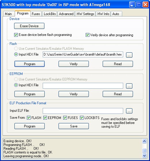
We choose the HEX file and press the Program Button to down load the code into the AVRJazz Mega168 board. Now it’s time to relax and enjoy your hard work by watching BRAM II Line Follower Robot in action:
The Final Thought
As you’ve learned from this BRAM II Line Follower Robot tutorial, to design and build the microcontroller based robot successfully, you need to use many of the microcontroller supported peripheral features (e.g. I/O, PWM, UART, ADC, TWI) at the same time, therefore having a good and solid understanding of how these peripheral work will help you solve most of the problem occur when building the microcontroller based robot.

Saturday, 21 September 2013

Working with Atmel AVR Microcontroller Basic Pulse Width Modulation (PWM) Peripheral

Pulse Width Modulation (PWM) is a technique widely used in modern switching circuit to control the amount of power given to the electrical device.  This method simply switches ON and OFF the power supplied to the electrical device rapidly. The average amount of energy received by the electrical device is corresponding to the ON and OFF period (duty cycle); therefore by varying the ON period i.e. longer or shorter, we could easily control the amount of energy received by the electrical device. The Light Emitting Diode (LED) will respond to this pulse by dimming or brighten its light while the electrical motor will respond to this pulse by turning its rotor slow or fast.

The above picture show a typical Pulse Width Modulation (PWM), the PWM duty cycle is the proportion of the signal “ON” time to one period (T) of the signal time. The duty cycle will be higher when the ON time is longer than the OFF time and vice versa. Duty cycle is expressed in percentage; therefore you could define the duty cycle of PWM signal as follow:


The 100% PWM duty cycle means it’s fully ON and we could say that 100% of the power or energy is delivered to the electrical device, while 15% duty cycle means only 15% of the power is being delivered to the electrical device. This average in power could be presented as average in voltage as follow:

The PWM signal normally has a fixed frequency (period) with a duty cycle that could vary from 0% to 100%. Now you understand that by just adjusting the PWM duty cycle we could easily control the LED brightness or the electrical motor spinning speed.
Today most of modern microcontroller has a build in PWM peripheral inside; this make generating PWM signal is become easy and straightforward, you could read more about non microcontroller PWM base generator on “The LM324 Quad Op-Amp Line Follower Robot with Pulse Width Modulation” article on this blog. On this tutorial we are going to use Atmel AVR ATMega168 microcontroller which support up to 6 PWM output simultaneously and at the end of this tutorial we will take advantage of all the available PWM peripheral to make a nice RGB LED Light and Sound Show.

The AVR Microcontroller PWM Peripheral
Most of the microcontroller PWM peripheral depends on the TIMER peripheral to provide the PWM signals frequency. The PWM peripheral will use the TIMER counter register (TCNT) as a digital step-up /down and continuously compare to the pre-determine duty cycle register (OCR – output compare register) value.

When TCNT equal to OCR value the wave generator circuit will set (ON) or reset (OFF) the corresponding microcontroller PWM I/O ports. The following picture show a simplified version of Atmel AVR ATMega168 microcontroller PWM peripheral (please refer to the Atmel ATMega48/88/168/328 datasheet for more information):

Each of the AVR ATMega168 microcontrollers TIMER has two PWM channels named channel A and channel B, where each channel has its own output compare register (OCR). From the diagram above you could see that both channel share the same TIMER counter register (TCNT), this mean you could only have one PWM frequency for each TIMER (TIMER0, TIMER1, and TIMER2) but you could have different duty cycle on each channel (A and B). The AVR ATMega48/88/168/328 microcontroller provides three PWM modes which are Fast PWM Mode, Phase Correct PWM Mode, and Phase and Frequency Correct Mode. The last mode is only available on TIMER1 (16-bit timer). Ok before we continue let’s list down the hardware and software needed for this tutorial:
1. AVRJazz Mega168 or AVRJazz Ultimate 28P board (I used in this project), you could also use any AVR ATMega168 board or bare ATMega168, whatever available to you (the electronics components listed here is just for the final project)
2. One Bread board
3. Resistors: 10K (1), 15K (1), and 18 (1)
4. One 10K Trimpot
5. Non polar Capacitor 0.1uF (3) and 0.01uF (1)
6. Polar Capacitor 220uF/16V (1) and 10uF/16V (1)
7. One 5 mm RGB LED
8. National Semiconductor LM386 IC
9. One white ping-pong ball for defusing the RGB LED light
10. One Speaker
11. The latest Atmel AVRStudio (in this project I used v4.18) and WinAVR GNU-C Compiler (in this project I used WinAVR 20100110)
12. AVR Microcontroller Programmer
13. Atmel ATMega48/88/168/328 and LM386 datasheet.


The AVR Fast PWM Mode
The AVR fast PWM mode could generate the most high frequency PWM waveform compared to the other two PWM modes (i.e. Phase Correct or Phase and Frequency Correct mode). This PWM mode simply uses the TIMER counter register (TCNTn, where n represent the TIMER 0, TIMER1, and TIMER2 respectively) incremental value which is start from 0×00 (BOTTOM) to 0xFF (8-bit TOP) or 0xFFFF (16-bit TOP).
When the TIMER counter register reach the output compare register (OCRnA or OCRnB) value then the wave generator circuit will CLEAR (logical low) the output compare bit channel (OCnA or OCnB). When the TIMER counter register value reach the TOP value then it will SET (logical high) the output compare bit channel and the whole process will repeat again from BOTTOM. This PWM generation process could be shown on this following diagram:

As shown on the diagram above, the behavior of output compare bit channel (OCnA or OCnB) output could be set to non-inverting (CLEAR and SET) or inverting (SET and CLEAR) mode by setting the compare match channel bit (COMnA1, COMnA0, COMnB1, and COMnB0) on Timer/Counter register A (TCCRnA). The Fast PWM mode could be set by setting the wave generation mode bit (WGM01 and WGM00) on Timer/Counter register A (TCCRnA) and WGM02 bit on TCCRnB register. When the TIMER counter register (TCNTn) equal to Output Compare Register (OCRnA or OCRnB) it will generate the Output Compare interrupt and when the TCNTn register reach TOP it will generate the TIMER overflow interrupt (TOV).

As you see at the Atmel AVR microcontroller PWM peripheral diagram above when we update the Output Compare Register (OCRnA and OCRnB) value, the value will be updated on the Output Compare Register Buffer first and when the TIMER0 Counter Register (TCNT0) reach TOP then the OCRn register will be updated with the OCRn buffer value and at the same time the Output Compare Bits (OCnA or OCnB) will be set.

On this following C code, we are going to use TIMER0 Fast PWM mode on both channel A and channel B.
//***************************************************************************
//  File Name  : avrpwm01.c
//  Version  : 1.0
//  Description  : AVR TIMER0 Fast PWM Mode
//  Author       : RWB
//  Target       : AVRJazz Ultimate 28PIN Board
//  Compiler     : AVR-GCC 4.3.3; avr-libc 1.6.7 (WinAVR 20100110)
//  IDE          : Atmel AVR Studio 4.18
//  Programmer   : AVRJazz Mega168 STK500 v2.0 Bootloader
//               : AVR Visual Studio 4.18, STK500 programmer
//  Last Updated : 21 March 2011
//***************************************************************************
#include <avr/io.h>
#include <util/delay.h>
int main(void)
{
  unsigned char duty_cyc_a,duty_cyc_b;
  // Initial PORT Used
  DDRD = 0b11111111;     // Set PORTD: Output
  PORTD = 0x00;
  // Initial TIMER0 Fast PWM
  // Fast PWM Frequency = fclk / (N * 256), Where N is the Prescaler
  // f_PWM = 11059200 / (64 * 256) = 675 Hz
  TCCR0A = 0b10100011; // Fast PWM 8 Bit, Clear OCA0/OCB0 on Compare Match, Set on TOP
  TCCR0B = 0b00000011; // Used 64 Prescaler
  TCNT0 = 0;           // Reset TCNT0
  OCR0A = 0;           // Initial the Output Compare register A & B
  OCR0B = 0;
  duty_cyc_a=0; // Initial Duty Cycle for Channel A
  duty_cyc_b=255; // Initial Duty Cycle for Channel B

  for(;;) {            // Loop Forever
    while(duty_cyc_a < 255) {
      OCR0A=duty_cyc_a++;
      OCR0B=duty_cyc_b--;
       _delay_ms(10);
    }

    while(duty_cyc_b < 255) {
      OCR0A=duty_cyc_a--;
      OCR0B=duty_cyc_b++;
      _delay_ms(10);
    }
  }

  return 0;         // Standard Return Code
}
/* EOF: avrpwm01.c */

The TIMER0 Fast PWM mode is activated by setting the Wave Generation Mode bits WGM02=0, WGM01=1, and WGM00 = 1 on TIMER0 Timer/Counter control Registers (TCCR0A and TCCR0B) as follow:
// Initial TIMER0 Fast PWM
// Fast PWM Frequency = fclk / (N * 256), Where N is the Prescaler
// f_PWM = 11059200 / (64 * 256) = 675 Hz
TCCR0A = 0b10100011; // Fast PWM 8 Bit, Clear OCA0/OCB0 on Compare Match, Set on TOP
TCCR0B = 0b00000011; // Used 64 Prescaler
Therefore by assigning the Clock Set Bit CS02 = 0, CS01 = 1, and CS00 = 1 respectively, we tell the TIMER0 to use 64 as a prescaler, therefore you could calculate the PWM frequency if we use 11059200 Hz external crystal as follow:
PWM Frequency = Freq Clock / (prescaler x 256) = 11059200 / (64 x 256) = 675 Hz
You could freely choose or experiment with any PWM frequency that work best with the electrical devices that you want to control with the Fast PWM mode signal.
One of disadvantage using the Fast PWM mode to generate the PWM signal is the PWM phase is shifted when we change the PWM duty cycle. This because when the TIMER0 Counter Register (TCNTn) reach TOP and start from BOTTOM it will always SET (or CLEAR) the Output Compare Bits (OCnA or OCnB) despite the Output Compare Register (OCRnA and OCRnB) value; therefore when we change the duty cycle in Fast PWM mode the PWM signal phase is always shifted as illustrated on this following diagram:

This make the Fast PWM mode is not suitable when we want to use for controlling the motor speed precisely; therefore on our next discussion we will correct this shifted phase effect by using the AVR microcontroller Phase Correct PWM mode for generating the PWM signal.
Now as you understand of how to use the Fast PWM mode on TIMER0, you could easily adapt this principal to TIMER1 (16-bit) and TIMER2 (8-bit). Please refer to the Atmel ATMega48/88/168/328 datasheet for complete information.
The AVR Phase Correct PWM Mode
Differ from the Fast PWM Mode, the Phase Correct PWM mode is using dual slope TIMER counter. Basically the TIMER counter register (TCNTn) will increase its value (up counter) from BOTTOM to TOP and then decrease its value (down counter) from TOP to BOTTOM. When the TIMER counter register equal to the Output Compare Register (OCRnA and OCRnB) then the wave generator bit will simply toggle the Output Compare channel (OCnA and OCnB) as shown on this following diagram:

As shown on the diagram above you could see that the Phase Correct PWM mode will have half of the PWM signal frequency compared to the fast PWM mode. Because of the dual slope technique used in the Phase Correct PWM mode to generate the PWM signal, therefore the phase correct PWM mode is more precision and suitable to be used as a motor controller, because as we change the PWM signal duty cycle the phase between each duty cycles remain the same as illustrated on this following diagram:


On this following C code, we are going to use TIMER0 Phase Correct PWM mode on both channel A and channel B.
//***************************************************************************
//  File Name  : avrpwm02.c
//  Version  : 1.0
//  Description  : AVR TIMER0 Phase Correct PWM Mode
//  Author       : RWB
//  Target       : AVRJazz Ultimate 28PIN Board
//  Compiler     : AVR-GCC 4.3.3; avr-libc 1.6.7 (WinAVR 20100110)
//  IDE          : Atmel AVR Studio 4.18
//  Programmer   : AVRJazz Mega168 STK500 v2.0 Bootloader
//               : AVR Visual Studio 4.18, STK500 programmer
//  Last Updated : 21 March 2011
//***************************************************************************
#include <avr/io.h>
#include <util/delay.h>
int main(void)
{
  unsigned char duty_cyc_a,duty_cyc_b;
  // Initial PORT Used
  DDRD = 0b11111111;     // Set PORTD: Output
  PORTD = 0x00;
  // Initial TIMER0 Phase Correct PWM
  // Fast PWM Frequency = fclk / (N * 510), Where N is the Prescaler
  // f_PWM = 11059200 / (64 * 510) = 338.82 Hz
  TCCR0A = 0b10100001; // Phase Correct PWM 8 Bit, Clear OCA0/OCB0 on Compare Match, Set on TOP
  TCCR0B = 0b00000011; // Used 64 Prescaler
  TCNT0 = 0;           // Reset TCNT0
  OCR0A = 0;           // Initial the Output Compare register A & B
  OCR0B = 0;
  duty_cyc_a=0;     // Initial Duty Cycle for Channel A
  duty_cyc_b=255;    // Initial Duty Cycle for Channel B

  for(;;) {            // Loop Forever
 while(duty_cyc_a < 255) {
   OCR0A=duty_cyc_a++;
   OCR0B=duty_cyc_b--;
   _delay_ms(10);
 }

 while(duty_cyc_b < 255) {
   OCR0A=duty_cyc_a--;
   OCR0B=duty_cyc_b++;
   _delay_ms(10);
 }
  }

  return 0;            // Standard Return Code
}
/* EOF: avrpwm02.c */


The TIMER0 Phase Correct PWM mode is activated by setting the Wave Generation Mode bits WGM02=0, WGM01=0, and WGM00 = 1 on TIMER0 Timer/Counter control Registers (TCCR0A and TCCR0B) as follow:
// Initial TIMER0 Phase Correct PWM
// Fast PWM Frequency = fclk / (N * 510), Where N is the Prescaler
// f_PWM = 11059200 / (64 * 510) = 338.82 Hz
TCCR0A = 0b10100001; // Phase Correct PWM 8 Bit, Clear OCA0/OCB0 on Compare Match, Set on TOP
TCCR0B = 0b00000011; // Used 64 Prescaler
Therefore by assigning the Clock Set Bit CS02 = 0, CS01 = 1, and CS00 = 1 respectively, we tell the TIMER0 to use 64 as a prescaler, therefore the Phase Correct PWM frequency could be calculated as follow:
PWM Frequency = Freq Clock / (prescaler x 510) = 11059200 / (64 x 510) = 338.82 Hz
Again you could easily adapt this principal to TIMER1 (16-bit) and TIMER2 (8-bit) as well (please refer to Atmel ATMega48/88/168/328 datasheet for complete information).
The AVR Phase and Frequency Correct PWM Mode
The Phase and Frequency Correct PWM Mode feature is only available on TIMER1 (16-bit). Basically the Phase and Frequency Correct PWM mode use the same dual slope technique used in Phase Correct PWM mode to generate the PWM signal. These two modes actually are identical if we never change the PWM signal frequency, but if we need to change the PWM signal frequency on fly, then we need to use the AVR ATMega168 microcontroller Phase and Frequency Correct mode to generate the PWM signal.

Differ from the Phase Correct PWM Mode, in Phase and Frequency Correct PWM Mode the Output Compare Register (OCRnA and OCRnB) is updated from the buffer when the Timer Counter Register (TCNTn) reaches BOTTOM instead of TOP in Phase Correct PWM Mode. The frequency could be change by changing the TOP value, here you could understand why we need to use the Phase and Frequency Correct PWM mode, because as we change the frequency and at the same time the PWM peripheral update the Output Compare register (OCRnA and OCRnB) then there will be a glitch in the PWM frequency signal.
In Phase and Frequency Correct PWM mode because the Output Compare Register is updated at the BOTTON therefore the rising and falling length of the PWM signal is always equal this result in frequency being corrected when we change the frequency on fly.

Typically in controlling the electrical device with PWM signal we seldom change the PWM frequency on fly, therefore the common application for this mode is to generate the sound. On this following C code example I used the Phase and Frequency Correct PWM to generated tone. Another example of using this PWM mode could be read in “AVR Twinkle-Twinkle Song Using PWM Project” article on this blog.
//***************************************************************************
//  File Name  : avrpwm03.c
//  Version  : 1.0
//  Description  : AVR TIMER0 Phase and Frequency Correct PWM Mode
//  Author       : RWB
//  Target       : AVRJazz Ultimate 28PIN Board
//  Compiler     : AVR-GCC 4.3.3; avr-libc 1.6.7 (WinAVR 20100110)
//  IDE          : Atmel AVR Studio 4.18
//  Programmer   : AVRJazz Mega168 STK500 v2.0 Bootloader
//               : AVR Visual Studio 4.18, STK500 programmer
//  Last Updated : 21 March 2011
//***************************************************************************
#include <avr/io.h>
#include <util/delay.h>
// Notes Frequency from http://www.phy.mtu.edu/~suits/notefreqs.html
// The Original frequency value (decimal) is converted to the integer value
#define C4  262
#define Cc4 277
#define D4  294
#define Dc4 311
#define E4  330
#define F4  349
#define Fc4 370
#define G4  392
#define Gc4 415
#define A4  440
#define Ac4 466
#define B4  494

#define C5  523
#define Cc5 554
#define D5  587
#define Dc5 622
#define E5  659
#define F5  698
#define Fc5 740
#define G5  783
#define Gc5 831
#define A5  880
#define Ac5 932
#define B5  988
#define C6  1047
// LED Display variables
unsigned char ledstat,led_out;
// PlayNotes function
void PlayNotes(unsigned int note_frequency,unsigned int duration)
{
   unsigned int top_value,duty_cycle;
   // Calculate the Top Value
   // TOP = Board Clock Frequency / (2 x N x Notes Frequency)
   // Where N is Prescler: 8
   topvalue=(F_CPU / (16 * note_frequency));
   // Reset the TIMER1 16 bit Counter
   TCNT1H = 0;
   TCNT1L = 0;

   // Set the TIMER1 Counter TOP value on ICR1H and ICR1L
   ICR1H = (top_value >> 8 ) & 0x00FF;
   ICR1L = top_value;   

   // Set the TIMER1 PWM Duty Cycle on OCR1AH and OCR1AL
   // Always use half of the TOP value (PWM Ducty Cycle ~ 50%)
   duty_cycle=top_value / 2;
   OCR1AH=(duty_cycle >> 8 ) & 0x00FF;
   OCR1AL=duty_cycle;
   // Turn ON the TIMER1 Prescaler of 8
   TCCR1B |= (1<<CS11); 

   // Notes Delay Duration
   _delay_ms(duration); 

   // Turn OFF the TIMER1 Prescaler of 8
   TCCR1B &= ~(1<<CS11);
   // Delay Between Each Notes 1/5 duration
   _delay_ms(duration * 1/5);
}
// Display LED function
void DisplayLED(void)
{
  if (ledstat) {
    PORTD=led_out;
    led_out=led_out << 1;
    if (led_out >= 0x80) ledstat=0;
  } else {
    PORTD=led_out;
    led_out=led_out >> 1;
    if (led_out <= 0x01) ledstat=1;
  }
}
int main(void)
{
  unsigned int notes[25]={C4,Cc4,D4,Dc4,E4,F4,Fc4,G4,Gc4,A4,Ac4,B4,
                          C5,Cc5,D5,Dc5,E5,F5,Fc5,G5,Gc5,A5,Ac5,B5,C6};
  int icount;
  unsigned char pstat;
  unsigned int idelay;
  // Initial PORT Used
  DDRD = 0b11111111;   // Set PORTD as Output
  PORTD = 0b00000000;
  DDRB = 0b11111110;   // Set PB0 as Input and other as Output
  PORTB = 0b00000000;
  // Initial the ADC Peripheral
  ADCSRA = (1<<ADEN) | (1<<ADPS2) | (1<<ADPS1);
  // Use Free running Mode
  ADCSRB = 0b00000000;
  // Disable digital input on Channel 0
  DIDR0 = 0b00000001;
  // Initial TIMER1 Phase and Frequency Correct PWM
  // Set the Timer/Counter Control Register
  TCCR1A = 0b11000000; // Set OC1A when up counting, Clear when down counting
  TCCR1B = 0b00010000; // Phase/Freq-correct PWM, top value = ICR1, Prescaler: Off              

  // Initial Variables
  icount=0;
  pstat=1;
  led_out=1;
  ledstat=1;
  for(;;) {            // Loop Forever
    // Reading User Trimpot on Analog Channel 0
   ADMUX=0;
   // Start conversion by setting ADSC on ADCSRA Register
   ADCSRA |= (1<<ADSC);
   // wait until convertion complete ADSC=0 -> Complete
   while (ADCSRA & (1<<ADSC));
   // Get the ADC Result
   idelay=ADCW;
    DisplayLED();
    if (pstat) {
   PlayNotes(notes[icount++],idelay);
   if (icount > 24) {
  icount=24;
  pstat=0;
      }
    } else {
   PlayNotes(notes[icount--],idelay);
   if (icount < 0) {
  icount=0;
  pstat=1;
      }
    }
  }

  return 0;            // Standard Return Code
}
/* EOF: avrpwm03.c */

To generate a controllable tone, we need to produce the exact frequency on each notes, the notes frequency could be found at this website address http://www.phy.mtu.edu/~suits/notefreqs.html. In order to generate the C5 note we have to produce the PWM frequency of 523.23 Hz at 50% duty cycle. Therefore by setting the Wave Generation Mode Bits WGM13=1, WGM12=0, WGM11=0, and WGM10=0 respectively, we choose the TIMER1 Phase and Frequency Correct PWM mode which has TOP value set on TIMER1 Input Capture Registers ICR1H and ICR1L; the Pulse Width is set on TIMER1 Output Compare Registers OCR1A and OCR1B.

With the precaler being set to 8 and board frequency of 1109200 Hz, we could easily calculate the TOP value of theC5 note as follow:
PWM Frequency = Freq Clock / (2 x N x TOP) = Freq Clock / (16 x TOP)
Or
TOP = Freq Clock / (16 x PWM Frequency) = 11059200 / (16 x 523) = 1322
Now by assigning the TOP value to the Input Capture Registers (ICR1H and ICR1L) and half of the TOP value to the Output Compare Register (OCR1AH and OCR1AL) we could produce the C5 notes with 50% duty cycle as shown on this following C code:
// Calculate the Top Value
// TOP = Board Clock Frequency / (2 x N x Notes Frequency)
// Where N is Prescler: 8
topvalue=(F_CPU / (16 * note_frequency));
// Set the TIMER1 Counter TOP value on ICR1H and ICR1L
ICR1H = (top_value >> 8 ) & 0x00FF;
ICR1L = top_value;
// Set the TIMER1 PWM Duty Cycle on OCR1AH and OCR1AL
// Always use half of the TOP value (PWM Ducty Cycle ~ 50%)
duty_cycle=top_value / 2;
OCR1AH=(duty_cycle >> 8 ) & 0x00FF;
OCR1AL=duty_cycle;
Because the ICR1H and ICR1L are the 8-bit registers, therefore we use the C language shift right operator to assign the upper 8-bit top_value to ICR1H and the lower 8-bit TOP value to ICR1L. We use similar principal to both OCR1H and OCR1L for the PWM duty cycle value (duty_cycle). The complete C code is implemented in PlayNotes() function, which accept the frequency and duration parameters to produce the needed sound. The AVR ATMega168 microcontroller ADC peripheral is used to control the playing notes delay by passing the trimpot voltage reading connected to ADC channel 0 (PC0), we could control the notes duration as shown on this following C code:
// Reading User Trimpot on Analog Channel 0
ADMUX=0;
// Start conversion by setting ADSC on ADCSRA Register
ADCSRA |= (1<<ADSC);
// wait until convertion complete ADSC=0 -> Complete
while (ADCSRA & (1<<ADSC));
// Get the ADC Result
idelay=ADCW;
...
...
PlayNotes(notes[icount++],idelay);
For more information about using Atmel AVR microcontroller ADC peripheral you could read “Analog to Digital Converter AVR C Programming” articles on this blog


The RGB LED Light and Sound Show
On this last tutorial we will put all together the AVR ATMega168 basic PWM lessons that we’ve learned and making some interesting RGB LED and Sound show as shown on this following schematic:

This RGB light and Sound show project used the well known LM386 linear amplifier IC from National Semiconductor which recently has been acquired by Texas Instrument (April 2011) to produce a quite loud sound from the TIMER1 Phase and Correct Frequency PWM mode through the speaker. The TIMER1 Output Compare Channel A (PB1) PWM signal is being passed through the passive low pass filter (is also called an integrator circuit for a non sinusoidal input signal such as square wave and triangle wave) in order to shape the square wave forms to become the sinusoidal wave forms before being amplified by the LM386 IC.
To make the low pass filter (LPF) become a good integrator circuit we have to choose the LPF cutoff frequency much less than the lowest frequency produced by the PWM signal but at the same time still produce an adequate signal level to drive the LM386 amplifier input. The cutoff frequency of LPF could be calculated as this following formula:
Frequency = 1 / (2 x pi x RC), where pi = 3.14159, R is resistance in Ohm, and C is capacitance in Farad
The lowest frequency produce by PWM signal is 262 Hz (C4 note), therefore by choosing R = 15K and C = 0.1uF, we could calculate the LPF cutoff frequency as follow:
Frequency = 1 / (2 x 3.14159 x 15000 x 0.0000001) = 106.10 Hz
This method is used to ensure that we could get a quite nice sound produced on the speaker instead of just using raw square wave signal as shown on this following oscilloscope picture:

Each of the RGB LED cathodes is driven by TIMER0 Fast PWM channel A, channel B, and TIMER2 Phase Correct PWM channel B respectively. The following is the complete C code for our RGB LED Light and Sound Show final project:
//***************************************************************************
//  File Name  : avrpwm04.c
//  Version  : 1.0
//  Description  : AVR TIMER0 Phase and Frequency Correct PWM Mode
//  Author       : RWB
//  Target       : AVRJazz Ultimate 28PIN Board
//  Compiler     : AVR-GCC 4.3.3; avr-libc 1.6.7 (WinAVR 20100110)
//  IDE          : Atmel AVR Studio 4.18
//  Programmer   : AVRJazz Mega168 STK500 v2.0 Bootloader
//               : AVR Visual Studio 4.18, STK500 programmer
//  Last Updated : 22 March 2011
//***************************************************************************
#include <avr/io.h>
#include <util/delay.h>
#include <avr/interrupt.h>
#include <stdlib.h>
// Notes Frequency from http://www.phy.mtu.edu/~suits/notefreqs.html
// The Original frequency value (decimal) is converted to the integer value
#define C4  262
#define Cc4 277
#define D4  294
#define Dc4 311
#define E4  330
#define F4  349
#define Fc4 370
#define G4  392
#define Gc4 415
#define A4  440
#define Ac4 466
#define B4  494

#define C5  523
#define Cc5 554
#define D5  587
#define Dc5 622
#define E5  659
#define F5  698
#define Fc5 740
#define G5  783
#define Gc5 831
#define A5  880
#define Ac5 932
#define B5  988
#define C6  1047
volatile unsigned char duty_cyc_a,duty_cyc_b, duty_cyc_c,led_a,led_b,led_c;
volatile unsigned int tempo;
// TIMER1 Overflow Interrupt
ISR(TIMER1_OVF_vect)
{
  cli();                  // Disable Interrupt
  // Reading User Trimpot on Analog Channel 0
  ADMUX = 0;
  // Start conversion by setting ADSC on ADCSRA Register
  ADCSRA |= (1<<ADSC);
  // wait until convertion complete ADSC=0 -> Complete
  while (ADCSRA & (1<<ADSC));
  // Get the ADC Result
  tempo=ADCW;      

  if (led_a) {
    if (duty_cyc_a < 255) {
     OCR0A=duty_cyc_a++;
    } else {
   led_a=0;
    }
  } else {
    if (duty_cyc_a > 0) {
     OCR0A=duty_cyc_a--;
    } else {
   led_a=1;
   duty_cyc_a=TCNT1L;
    }
  }

  if (led_b) {
    if (duty_cyc_b < 255) {
     OCR0B=duty_cyc_b++;
    } else {
   led_b=0;
    }
  } else {
    if (duty_cyc_b > 0) {
     OCR0B=duty_cyc_b--;
    } else {
   led_b=1;
      duty_cyc_b=(unsigned char) rand() % 255; ;
    }
  }

  if (led_c) {
    if (duty_cyc_c < 255) {
      OCR2B=duty_cyc_c++;
    } else {
   led_c=0;
 }
  } else {
    if (duty_cyc_c > 0) {
      OCR2B=duty_cyc_c--;
    } else {
   led_c=1;
      duty_cyc_c=TCNT1H;
    }
  }
  sei();                      // Enable Interrupt
}
// PlayNotes function
void PlayNotes(unsigned int note_frequency,unsigned int duration)
{
   unsigned int top_value,duty_cycle;
   // Calculate the Top Value
   // TOP = Board Clock Frequency / (2 x N x Notes Frequency)
   // Where N is Prescler: 8
   topvalue=(F_CPU / (16 * note_frequency));
   // Reset the TIMER1 16 bit Counter
   TCNT1H = 0;
   TCNT1L = 0;

   // Set the TIMER1 Counter TOP value on ICR1H and ICR1L
   ICR1H = (top_value >> 8 ) & 0x00FF;
   ICR1L = top_value;   

   // Set the TIMER1 PWM Duty Cycle on OCR1AH and OCR1AL
   // Always use half of the TOP value (PWM Ducty Cycle ~ 50%)
   duty_cycle=top_value / 2;
   OCR1AH=(duty_cycle >> 8 ) & 0x00FF;
   OCR1AL=duty_cycle;
   // Turn ON the TIMER1 Prescaler of 8
   TCCR1B |= (1<<CS11); 

   // Notes Delay Duration
   _delay_ms(duration); 

   // Turn OFF the TIMER1 Prescaler of 8
   TCCR1B &= ~(1<<CS11);
   // Delay Between Each Notes
   _delay_ms(duration * 1/5);
}
int main(void)
{
  unsigned char song_index;
  // Initial PORT Used
  DDRD = 0b11111111;   // Set PORTD as Output
  PORTD = 0b00000000;
  DDRB = 0b11111110;   // Set PB0 as Input and other as Output
  PORTB = 0b00000000;
  // Initial the ADC Peripheral
  ADCSRA = (1<<ADEN) | (1<<ADPS2) | (1<<ADPS1);
  // Use Free running Mode
  ADCSRB = 0b00000000;
  // Disable digital input on Channel 0
  DIDR0 = 0b00000001;
  // Initial TIMER0 Fast PWM
  // Fast PWM Frequency = fclk / (N * 256), Where N is the prescaler
  // f_PWM = 11059200 / (64 * 256) = 675 Hz
  TCCR0A = 0b10100011; // Fast PWM 8 Bit, Clear OCA0/OCB0 on Compare Match, Set on TOP
  TCCR0B = 0b00000011; // Used 64 Prescaler
  TCNT0 = 0;           // Reset TCNT0
  OCR0A = 0;           // Initial the Output Compare register A & B
  OCR0B = 0;
  // Initial TIMER1 Phase and Frequency Correct PWM
  // Set the Timer/Counter Control Register
  TCCR1A = 0b11000000; // Set OC1A when up counting, Clear when down counting
  TCCR1B = 0b00010000; // Phase/Freq-correct PWM, top value = ICR1, Prescaler: Off              

  TIMSK1 = (1<<TOIE1); // Enable Overflow Interrupt
  // Initial TIMER2 Phase Correct PWM Mode
  // Phase Correct PWM Frequency = fclk / (N * 512), Where N is the prescaler
  // f_PWM = 11059200 / (64 * 512) = 337.5 Hz
  TCCR2A = 0b00100001; // Fast PWM 8 Bit, Clear OC2B on Compare Match, Set on TOP
  TCCR2B = 0b00000011; // Used 64 Prescaler
  TCNT2 = 0;           // Reset TCNT2
  OCR2B = 0;           // Initial the Output Compare register A & B
  duty_cyc_a=(unsigned char) rand() % 255;
  led_a=1;
  duty_cyc_b=(unsigned char) rand() % 255;
  led_b=1;
  duty_cyc_c=(unsigned char) rand() % 255;
  led_c=1;
  sei();               // Enable Interrupt
  song_index=0;
  tempo=0;

  for(;;) {            // Loop Forever
 // Playing "What a Wonderfull World" Song Notes
 PlayNotes(G4,300 + tempo); PlayNotes(A4,100 + tempo);
        PlayNotes(C5,500 + tempo); PlayNotes(C5,450 + tempo);
 PlayNotes(G5,1150 + tempo); PlayNotes(A5,350 + tempo);
        PlayNotes(A5,350 + tempo); PlayNotes(A5,150 + tempo);
 PlayNotes(G5,1150 + tempo); PlayNotes(F5,450 + tempo);
        PlayNotes(F5,300 + tempo); PlayNotes(F5,250 + tempo);
 PlayNotes(E5,1150 + tempo); PlayNotes(D5,600 + tempo);
        PlayNotes(E5,175 + tempo); PlayNotes(D5,100 + tempo);
 PlayNotes(C5,1050 + tempo);
 PlayNotes(C5,550 + tempo); PlayNotes(C5,175 + tempo);
        PlayNotes(C5,100 + tempo); PlayNotes(C5,100 + tempo);
 PlayNotes(C5,150 + tempo); PlayNotes(C5,1300 + tempo);
        PlayNotes(C5,600 + tempo); PlayNotes(B4,200 + tempo);
 PlayNotes(C5,200); PlayNotes(D5,200 + tempo);
 if (song_index >= 1) {
   PlayNotes(C5,1600 + tempo);
   if (song_index == 3) {
     _delay_ms(100 + tempo);
     PlayNotes(C5,550 + tempo); PlayNotes(C5,175 + tempo);
            PlayNotes(C5,100 + tempo); PlayNotes(C5,100 + tempo);
     PlayNotes(C5,150 + tempo); PlayNotes(C5,1300 + tempo);
            PlayNotes(C5,800 + tempo); PlayNotes(B4,400 + tempo);
     PlayNotes(C5,300 + tempo); PlayNotes(D5,300 + tempo);
            PlayNotes(C5,2300 + tempo);
     song_index = 0;
   } else {
     song_index=2;
      }
    } else {
   PlayNotes(E5,1100 + tempo); PlayNotes(E5,800 + tempo);
          PlayNotes(D5,1600 + tempo);
   song_index=1;
    }
    if (song_index == 2) {
      _delay_ms(100 + tempo);
      PlayNotes(C5,450 + tempo); PlayNotes(D5,150 + tempo);
      PlayNotes(D5,50 + tempo); PlayNotes(D5,50 + tempo);
      PlayNotes(D5,1 + tempo); PlayNotes(D5,1000 + tempo);
      PlayNotes(G4,450 + tempo); PlayNotes(E5,150 + tempo);
      PlayNotes(E5,50 + tempo); PlayNotes(E5,50 + tempo);
      PlayNotes(E5,1 + tempo); PlayNotes(E5,1000 + tempo);
      PlayNotes(C5,350 + tempo); PlayNotes(D5,250 + tempo);
      PlayNotes(D5,100 + tempo); PlayNotes(D5,75 + tempo);
      PlayNotes(D5,350 + tempo); PlayNotes(C5,150 + tempo);
      PlayNotes(D5,250 + tempo); PlayNotes(E5,1000 + tempo);
      PlayNotes(E5,250 + tempo); PlayNotes(G5,175 + tempo);
      PlayNotes(A5,450 + tempo); PlayNotes(A5,100 + tempo);
      PlayNotes(E5,150 + tempo); PlayNotes(G5,1000 + tempo);
      PlayNotes(A5,100 + tempo); PlayNotes(A5,50 + tempo);
      PlayNotes(E5,150 + tempo); PlayNotes(G5,1000 + tempo); 

      PlayNotes(A5,100 + tempo); PlayNotes(A5,50 + tempo);
      PlayNotes(E5,150 + tempo); PlayNotes(G5,1000 + tempo);
      PlayNotes(F5,450 + tempo); PlayNotes(E5,650);
      PlayNotes(D5,1300 + tempo);
      song_index =3;
    }
  }

  return 0;            // Standard Return Code
}
/* EOF: avrpwm04.c */
From the C code above you could see that we use all the available AVR ATMega168 microcontroller PWM sources to drive both the RGB LED and at the same time playing “What a Wonderful World” song. By using the TIMER1 overflow interrupt (TOIE1=1 in TIMER1 interrupt mask register TIMSK1) we could display the RGB LED and at the same time playing the song notes.
The RGB LED PWM duty cycle is achieved by assigning both random value and the 16-bit TIMER1 counter value (TCNT1H and TCNT1L) to the Output Compare Register (OCRn) in ISR(TIMER1_OVF_vect) function routine. With this method we could get the desired RGB LED light effect which is depend on the song notes. Of course you could experiment with other register value as well (e.g . ICR1H and ICR1L registers).
Now it’s time to watch all the basic AVR PWM experiments we’ve done on this following video: