One of the frustrating part in learning AVR microcontroller for the
beginners is the AVR microcontroller programmer. The question is how to
program my AVR mircrocontroller; actually if you googling on the
internet and search for AVR ISP Programmer there are plenty information;
start from simply using your PC parallel port to the sophisticated
Atmel owned AVRISP mkII programmer. This will
rise another question; which one should I choose? Well, if you are
looking for the Atmel AVR programmer you have to consider how many AVR
devices does this programmer software support and how this programmer
hardware will connect to your PC/Notebook, of course the best and the
complete one will be the Atmel own AVR programmer.
The well known open sources AVR ISP programmer is released by Atmel called AVR911: AVR Open-source Programmer (is that just a coincident they use the number 911, therefore you can see how important this topics is) and the hardware schema you could find on their application note AVR910: In-System Programming. The original schema use the old AT90S1200 and both the firmware (at90isp_ver23.asm) and the downloader (AVROSP.exe) only support a view old devices, fortunately there are peoples out there that keep this application note updated with the current devices.
In this project I will use the AVRJazz Tiny2313 board from ermicro as the basic board for the programmer and AVR ATtiny13 microcontroller as the target for the programmer. The firmware is taken from Klaus Leidinger at mikrocontroller-projekte.de and I made some modification to the source code, so it can work with AVRJazz Tiny2313 board; this little changes is mainly on the ATTiny2313 microcontroller type (originally AT90S2313), crystal oscillator frequency (originally 7.3728 mHz), the LED’s routines (originally using dual color LED attached to the PORT B3 and B0) and the healcheck function to blink the board’s LED 5 times when it start. For the complete source code and the hex code you can download from here.
Although the firmware can work very well with the Atmel’s AVRPROG that come with the AVR Studio 4 (from menu Tools -> Avr Prog…), but this programmer only support a view devices; beside Atmel look likes will not update this program anymore, the last time they update the AVRPROG (version 1.40) mainly just for supporting their new AVR Butterfly evaluation board which is using ATMega169. Therefore I choose AvrOspII from Mike Henning for the latest windows programmer version that supporting the AVR911 protocol; this programmer software support mostly used AVR microcontroller devices.
The following is the hardware diagram, cable connection from PORTB AVRJazz Tiny2313 board (see the AVRJazz Tiny2313 schema above) and the schema for ATtiny13 used in this project:

For the purpose of this project I will use the AVR ATtiny13 fast PWM mode feature for dimming the LED1 connected to the PIN 5 (OC0A); the following is the AVR assembler code:
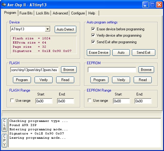
After compiling the sample code above on the AVR Studio 4 than start the AvrOspII program; if all connected then the programmer will automatically detect the target ATtiny13 microcontroller or you can click the Auto Detect button.

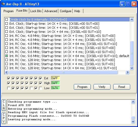
Before you download the hex program check the Fuse Bits on the Fuse Bits tab, make sure you uncheck the Divide clock by 8 internally; [CKDIV8=0] and use the default Internal RC oscillator 9.6 Mhz, click the Program button to change the Fuse Bits and click the Read button again to make sure it’s already change.

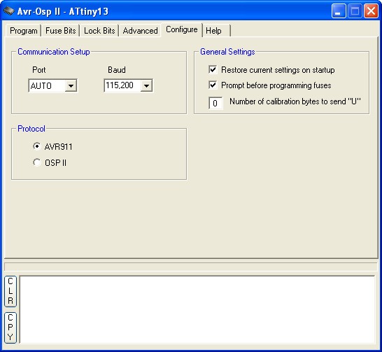
Also check the configuration on the Configure tab as follow:

The Port is set to AUTO, baud rate is set to 115200 and the protocol is set to AVR911. Checked all the Auto Program setting (Erase, Verified and Exit) on the Program tab, load your hex file on the Flash fill in box and click the Auto button to start download the hex file into the target AVR ATtiny13.
The well known open sources AVR ISP programmer is released by Atmel called AVR911: AVR Open-source Programmer (is that just a coincident they use the number 911, therefore you can see how important this topics is) and the hardware schema you could find on their application note AVR910: In-System Programming. The original schema use the old AT90S1200 and both the firmware (at90isp_ver23.asm) and the downloader (AVROSP.exe) only support a view old devices, fortunately there are peoples out there that keep this application note updated with the current devices.
In this project I will use the AVRJazz Tiny2313 board from ermicro as the basic board for the programmer and AVR ATtiny13 microcontroller as the target for the programmer. The firmware is taken from Klaus Leidinger at mikrocontroller-projekte.de and I made some modification to the source code, so it can work with AVRJazz Tiny2313 board; this little changes is mainly on the ATTiny2313 microcontroller type (originally AT90S2313), crystal oscillator frequency (originally 7.3728 mHz), the LED’s routines (originally using dual color LED attached to the PORT B3 and B0) and the healcheck function to blink the board’s LED 5 times when it start. For the complete source code and the hex code you can download from here.
Although the firmware can work very well with the Atmel’s AVRPROG that come with the AVR Studio 4 (from menu Tools -> Avr Prog…), but this programmer only support a view devices; beside Atmel look likes will not update this program anymore, the last time they update the AVRPROG (version 1.40) mainly just for supporting their new AVR Butterfly evaluation board which is using ATMega169. Therefore I choose AvrOspII from Mike Henning for the latest windows programmer version that supporting the AVR911 protocol; this programmer software support mostly used AVR microcontroller devices.
The following is the hardware diagram, cable connection from PORTB AVRJazz Tiny2313 board (see the AVRJazz Tiny2313 schema above) and the schema for ATtiny13 used in this project:

For the purpose of this project I will use the AVR ATtiny13 fast PWM mode feature for dimming the LED1 connected to the PIN 5 (OC0A); the following is the AVR assembler code:
;*********************************************************************
; Program       : tiny13pwm.asm
; Description   : Tiny13 Fast PWM Mode demo
; Last Updated  : 30 November 2008
; Author        : RWB
; IDE/Compiler  : Atmel AVR Studio 4.14
; Programmer    : AvrOspII v5.47 from Mike Henning
;               : AVRJazz Tiny2313 Board with firmware
;               : Avr910_2313_v38b_01.asm Modified by RWB from
;               : Klaus Leidinger(mikrocontroller-projekte.de)
;*********************************************************************
.include "tn13def.inc"
; The Tiny13 Default Frequency Clock
.equ F_CPU = 9600000
.cseg
; Start on the flash ram's address 0
.org 0
main:   ldi R24,RAMEND         ; Initial Stack Pointer
 out SPL,R24            ; SP = RAMEND
; Initial I/O
        ldi   R16,0xFF
        out   DDRB,R16         ; DDRB=0xFF
; Initial PWM
        ldi   R16,0b10000011
 out   TCCR0A,R16       ; TCCR0A = 0b10000011
 ldi   R16,0b00000001
 out   TCCR0B,R16       ; TCCR0B = 0b00000001
repeat: ldi   R16,255          ; R16 = 255
bright: inc   R16              ; R16 = R16 + 1
        out   OCR0A,R16        ; OCR0A = R16
 ldi   R19,1
 rcall delay_func       ; Call Delay Function Parameter R19 = 1
        cpi   R16,255
 brne  bright           ; if (R16 <> 255) goto bright label
 out   OCR0A,R16        ; OCR0A = R16
 ldi   R19,1
 rcall delay_func       ; Call Delay Function Parameter R19 = 1
 clr   R16              ; R16 = 0
dark:   dec   R16              ; R16 = R16 - 1
        out   OCR0A,R16        ; OCR0A = R16
 ldi   R19,1
 rcall delay_func       ; Call Delay Function Parameter R19
        cpi   R16,0
 brne  dark             ; if (R16 <> 0) goto dark label
 out   OCR0A,R16        ; OCR0A = R16
 ldi   R19,50
 rcall delay_func       ; Call Delay Function Parameter R19
 rjmp  repeat
; Simple Delay Function
delay_func:
delay0: ldi   R20,25     ; R20 = 25
delay1: ldi   R21,255    ; R21 = 255
delay2: dec   R21        ; Descrease R21
 brne  delay2     ; if (R20 != 0) goto delay2 label
        dec   R20        ; Decrease R20
        brne  delay1     ; if (R20 != 0) goto delay1 label
 dec   R19        ; Decrease R19
 brne  delay0     ; if (R19 != 0) goto delay0 label
 ret              ; Return to the caller
.exit
After compiling the sample code above on the AVR Studio 4 than start the AvrOspII program; if all connected then the programmer will automatically detect the target ATtiny13 microcontroller or you can click the Auto Detect button.

Before you download the hex program check the Fuse Bits on the Fuse Bits tab, make sure you uncheck the Divide clock by 8 internally; [CKDIV8=0] and use the default Internal RC oscillator 9.6 Mhz, click the Program button to change the Fuse Bits and click the Read button again to make sure it’s already change.

Also check the configuration on the Configure tab as follow:

The Port is set to AUTO, baud rate is set to 115200 and the protocol is set to AVR911. Checked all the Auto Program setting (Erase, Verified and Exit) on the Program tab, load your hex file on the Flash fill in box and click the Auto button to start download the hex file into the target AVR ATtiny13.
0 comments:
Post a Comment